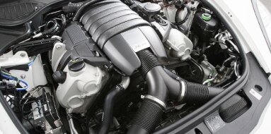
Mitsubishi 4M50 Specifications
| Engine Model: Mitsubishi 4M50 |
| Engine Type: 4-cycle 4-cylinder DOHC 16-valve turbocharged liquid-cooled diesel |
| Total Displacement: 299 cu.in (4.89 L) |
| Rated Engine Power: 130-190 Hp (96-140 kW) at 2700 rpm |
| Fuel System Type: Common rail direct injection |
____________________________________________________________________________________
The Mitsubishi 4M50 is a 4.9-liter, inline
four-cylinder diesel engine distinguished by its dual overhead camshaft (DOHC)
design and a four-valve-per-cylinder cylinder head. As a member of the
Mitsubishi “M-Series” engine family, it was engineered to provide a balance of
robust power output, fuel efficiency, and durability for medium-duty commercial
applications. The powerplant is defined by its advanced common-rail direct
injection (CRDi) system, which enables precise fuel metering and high-pressure
injection, contributing to reduced emissions and improved torque characteristics
across the operating range.
This engine was developed to succeed earlier powerplants in the Mitsubishi Fuso
Canter and Fighter truck ranges, addressing the need for greater power density
and compliance with progressively stringent emissions regulations. The
architecture incorporates a reinforced cylinder block, gear-driven valvetrain,
and integrated balance shafts to manage vibration inherent in a
large-displacement four-cylinder configuration. Its design prioritizes
serviceability and structural rigidity, making it a preferred power unit for
applications demanding consistent performance under sustained load conditions.
The 4M50 is a turbocharged and intercooled, water-cooled, four-stroke diesel
engine configured for longitudinal mounting in rear-wheel-drive and
all-wheel-drive commercial vehicle chassis. The engine utilizes a high-pressure
common-rail fuel system with electronic control for injection timing and
duration.
Engine Type: Inline-4, 4-cycle, water-cooled, turbocharged with intercooler.
Valvetrain: DOHC, 16-valve (4 valves per cylinder) with gear-driven camshafts.
Displacement: 4.899 L (4,899 cc / 299.0 cu.in).
Bore: 114.0 mm (4.49 in).
Stroke: 120.0 mm (4.72 in).
Compression Ratio: 17.5:1.
Firing Order: 1-3-4-2.
Aspiration: Single turbocharger with air-to-air intercooler.
Power output varies significantly based on application, emission standard (Euro
III, Euro IV, Euro V), and tuning configuration. The engine management system
adapts fuel delivery to achieve different output levels for specific vehicle
applications.
Power Ratings:
- 96 kW (130 hp) at 2,700 rpm (low-output industrial configuration).
- 110 kW (147 hp) at 2,700 rpm (standard medium-duty truck configuration).
- 130 kW (175 hp) at 2,700 rpm (high-output truck configuration).
- 140 kW (190 hp) at 2,800 rpm (maximum industrial configuration).
Torque Output:
- 400 Nm (295 lb-ft) at 1,600-2,200 rpm (low-output configuration).
- 470 Nm (347 lb-ft) at 1,600-2,200 rpm (standard configuration).
- 520 Nm (384 lb-ft) at 1,600-2,200 rpm (high-output configuration).
0The cylinder block is constructed from high-strength
cast iron with a deep-skirt design extending below the crankshaft centerline,
providing exceptional rigidity for the high cylinder pressures generated by the
turbocharged common-rail system. The block features an enclosed, reinforced
structure with thick bulkheads at each main bearing journal to minimize bore
distortion under high combustion loads.
The cylinder bores are machined directly into the block casting with a
plateau-honed surface finish that promotes oil retention and reduces friction
with the piston rings. The block incorporates a siamesed bore configuration
where adjacent cylinders share common walls, increasing structural rigidity and
reducing overall engine length compared to a design with water passages between
each cylinder. Water jackets surround the upper portion of each cylinder bore to
provide concentrated cooling at the area of highest thermal stress. The
crankcase is reinforced with transverse ribs cast into the external surfaces to
dampen vibration and noise emissions.
Material: Cast iron.
Bore Diameter: 114.0 mm (4.49 in).
Cylinder Arrangement: Siamesed bores, inline.
Main Bearing Quantity: 5.
Main Bearing Cap Design: Cast iron, cross-bolted on center three caps.
Balance Shafts: Dual counter-rotating balance shafts located in the crankcase,
gear-driven from the crankshaft.
The cylinder head is a cross-flow, aluminum alloy
casting with a DOHC valvetrain operating 16 valves. Each cylinder features two
intake valves and two exhaust valves arranged in a pent-roof combustion chamber
configuration. This design centralizes the fuel injector nozzle within the
combustion chamber, promoting optimal air-fuel mixing and efficient combustion.
The two camshafts - one for the intake valves and one for the exhaust valves -
are driven by a gear train from the crankshaft. A single idler gear mounted on
the cylinder block transfers drive from the crankshaft gear to the camshaft
gears. This gear-driven valvetrain provides precise valve timing control without
the stretch or replacement requirements associated with chain or belt systems.
The camshafts are supported in five bearing journals machined directly into the
cylinder head casting, with bearing caps of identical construction to ensure
uniform clamping.
Valve actuation is accomplished via roller-type cam followers (bucket tappets)
that incorporate an automatic hydraulic lash adjustment mechanism. The hydraulic
lash adjusters maintain zero valve clearance throughout the engine’s service
life, eliminating manual adjustment intervals and reducing valvetrain noise. The
valve seats are pressed-in inserts of heat-resistant material, with intake seats
of sintered iron and exhaust seats of a nickel-based alloy to withstand elevated
temperatures.
Head Material: Aluminum alloy
Valve Configuration: DOHC, 4 valves per cylinder
Valve Diameter (Intake): 36.0 mm (1.42 in)
Valve Diameter (Exhaust): 32.0 mm (1.26 in)
Valve Stem Diameter: 7.0 mm (0.28 in)
Valve Seat Angle: 45 degrees
Camshaft Drive: Gear train with helical-cut gears
Hydraulic Lash Adjusters: Yes, integrated into roller followers
The fuel system is a third-generation common-rail
direct injection (CRDi) system operating at pressures up to 1,600 bar (23,206
psi). A high-pressure supply pump - a gear-driven, radial-piston design - draws
fuel from the tank through a water-separating primary filter and delivers it to
the common rail accumulator mounted on the cylinder head. The common rail stores
fuel at injection pressure and supplies each of the four fuel injectors via
individual high-pressure lines.
Electronically controlled solenoid or piezoelectric injectors (depending on
generation) deliver fuel directly into the combustion chambers in multiple
injection events per combustion cycle. The engine control unit (ECU) governs
injection timing, injection pressure, and the number of injection events -
pre-injection, main injection, and post-injection - based on inputs from the
crankshaft position sensor, camshaft position sensor, boost pressure sensor,
coolant temperature sensor, and accelerator pedal position sensor. The system
utilizes a closed-loop feedback strategy based on oxygen sensors and a
differential pressure sensor across the diesel particulate filter (where fitted)
to optimize combustion and manage aftertreatment regeneration.
Injection Type: Common-rail direct injection
Maximum Injection Pressure: 1,600 bar (23,206 psi)
Injector Type: Solenoid or piezoelectric (generation-dependent)
High-Pressure Pump Type: Radial-piston, three-cylinder
Fuel Filtration: Primary water-separating filter plus secondary high-efficiency
filter
Fuel Requirement: Diesel fuel meeting EN 590 or equivalent specification
The lubrication system is a fully pressurized, wet-sump
design with a trochoid-type oil pump mounted externally on the front of the
cylinder block and driven directly by the crankshaft gear. This external pump
configuration simplifies service access and reduces the number of internal oil
passages required within the block casting.
Oil is drawn from the steel-constructed oil pan through a strainer-type pickup
and pressurized by the pump before passing through a full-flow, replaceable oil
filter. The filter head incorporates an integral oil cooler, a water-to-oil heat
exchanger that maintains oil temperature within operational limits. Pressurized
oil is delivered to the main oil gallery cast into the cylinder block, from
which it branches to the crankshaft main bearings, connecting rod bearings,
camshaft bearings, and hydraulic lash adjusters. Piston cooling jets - dedicated
oil nozzles - are mounted in the crankcase and direct a continuous stream of oil
to the underside of each piston crown to manage thermal loads under high output
conditions.
A pressure relief valve bypasses excess oil flow back to the oil pan when system
pressure exceeds the calibrated limit. The lubrication system capacity is sized
to accommodate the thermal demands of turbocharged operation and extended
service intervals.
Oil Type: Diesel engine oil meeting ACEA E4, E7, or API CJ-4; SAE 10W-30 or
15W-40.
Oil Capacity (with filter): 12.5 L (13.2 US qt).
Oil Pressure (at idle): 100 kPa (14.5 psi) minimum.
Oil Pressure (at rated speed): 350-450 kPa (51-65 psi).
Oil Pump Type: Trochoid (internal-external gear), crankshaft-driven.
Piston Cooling: Oil jets directed at piston undercrowns.
The cooling system is a pressurized, liquid-cooled
design with a belt-driven centrifugal water pump mounted on the front of the
cylinder block. Coolant circulates from the pump into the cylinder block water
jacket, passing upward through the siamesed cylinder bores and into the cylinder
head. The water jacket configuration directs flow preferentially to the exhaust
valve bridge areas and the injector boss regions within the cylinder head, where
thermal loading is highest.
A wax-pellet thermostat mounted in a housing on the front of the cylinder head
regulates coolant flow to the radiator, with a bypass circuit that permits
warm-up circulation without radiator flow. The cooling system incorporates a
separate expansion tank with a pressure-rated cap to manage coolant expansion
and system pressurization. The radiator is a cross-flow, aluminum-plastic
construction with a high-efficiency multi-louvered fin design. An electric or
viscous-drive fan (depending on vehicle application) provides forced airflow
through the radiator and charge air cooler.
A separate coolant circuit supplies the oil cooler mounted on the filter head,
with coolant flowing through the oil cooler before returning to the water pump
inlet. The cooling system capacity is specified to maintain stable operating
temperatures under maximum gross vehicle weight conditions and sustained highway
operation.
Coolant Type: Ethylene-glycol based antifreeze meeting Mitsubishi specification
Coolant Capacity: 13.0-15.0 L (13.7-15.9 US qt) depending on radiator
configuration
Thermostat Opening Temperature: 82 °C (180 °F)
Thermostat Full Opening Temperature: 95 °C (203 °F)
Radiator Cap Pressure: 110 kPa (16.0 psi)
Water Pump Type: Centrifugal, belt-driven
| Intake and Exhaust Systems |
Intake System: The intake system incorporates a
paper-element air cleaner with an integrated restriction indicator. Filtered air
passes through a mass air flow (MAF) sensor before entering the single-stage
turbocharger compressor housing. Compressed air passes through an air-to-air
intercooler (charge air cooler) mounted in front of the radiator, reducing
intake air temperature before entering the intake manifold. The intake manifold
is a fabricated aluminum or composite plastic design with equal-length runners
to each cylinder.
Exhaust System: The exhaust manifold is a cast iron, equal-length design that
combines the exhaust ports from all four cylinders into a single inlet for the
turbocharger turbine housing. The turbocharger is a wastegate-controlled unit
with a fixed-geometry turbine housing. Exhaust gas recirculation (EGR) is
employed on emissions-compliant variants, with an EGR cooler and electronically
controlled EGR valve diverting a portion of exhaust flow back to the intake
manifold to reduce combustion temperatures and nitrogen oxide formation.
Turbocharger: Single-stage, fixed-geometry turbocharger
with wastegate. Compressor housing size and turbine A/R ratio vary with output
configuration. Maximum boost pressure: 120-150 kPa (17.4-21.8 psi) depending on
tuning.
Engine Management: The engine control unit is a 32-bit microprocessor managing
fuel injection, EGR operation, turbocharger boost control, and aftertreatment
systems. The ECU communicates with vehicle systems via CAN bus protocol.
Overall Length: 850 mm (33.5 in)
Overall Width: 720 mm (28.3 in)
Overall Height: 880 mm (34.6 in)
Dry Weight (complete engine): 380 kg (838 lb)
Engine Oil Change: 10,000 km (6,200 mi) or 500
operating hours. Engine Oil Filter Change: At every oil change. Fuel Filter
Replacement: 20,000 km (12,400 mi) or 1 year.
Air Filter Element Replacement: When restriction indicator shows or 20,000 km
(12,400 mi).
Coolant Replacement: 80,000 km (49,700 mi) or 4 years. Valve Clearance
Adjustment: Not required (hydraulic lash adjusters). Timing Gear Inspection: No
scheduled replacement; gear backlash inspection at major overhaul.
Drive Belt (Accessory) Replacement: 60,000 km (37,300 mi). EGR Cooler Cleaning:
As indicated by diagnostic trouble codes or performance degradation. Fuel
Injector Replacement: 200,000 km (124,000 mi) inspection; replacement as
required by performance testing.
Cylinder Head Bolts (M12 x 1.75), 1st pass: 50 Nm (37
lb-ft)
Cylinder Head Bolts (M12 x 1.75), 2nd pass: 100 Nm (74 lb-ft)
Main Bearing Cap Bolts (M12 x 1.5): 50 Nm (37 lb-ft)
Cross-bolts (M8 x 1.25): 25 Nm (18 lb-ft)
Connecting Rod Cap Bolts (M9 x 1.25): 30 Nm (22 lb-ft)
Camshaft Bearing Cap Bolts (M8 x 1.25): 25 Nm (18 lb-ft)
Intake Manifold Bolts (M8 x 1.25): 25 Nm (18 lb-ft)
Exhaust Manifold Nuts (M8 x 1.25): 30 Nm (22 lb-ft)
Turbocharger Mounting Nuts (M10 x 1.25): 50 Nm (37 lb-ft)
Fuel Injector Clamp Bolts (M6 x 1.0): 12 Nm (106 lb-in)
High-Pressure Fuel Line Fittings: 25 Nm (18 lb-ft)
Oil Pan Bolts (M8 x 1.25): 20 Nm (15 lb-ft)
Water Pump Bolts (M8 x 1.25): 20 Nm (15 lb-ft)
Crankshaft Pulley Bolt (M20 x 1.5): 200 Nm (148 lb-ft)
Flywheel Bolts (M12 x 1.5): 70 Nm (52 lb-ft)
Engine Mounting Bracket Bolts (M12 x 1.5): 80 Nm (59 lb-ft)
The Mitsubishi 4M50 engine was deployed across a range
of medium-duty commercial vehicles and industrial equipment where durability and
a high power-to-weight ratio were required. Its primary application was in the
Mitsubishi Fuso Canter and Fighter truck ranges.
Mitsubishi Fuso Canter (FE, FG Series):
The 4M50 powered various iterations of the Canter medium-duty truck,
particularly in the 5-tonne to 8-tonne gross vehicle weight classes.
Applications included the Canter FE85, FE9, and FG4x4 cab-over models. Output
configurations in the Canter ranged from 110 kW (147 hp) to 130 kW (175 hp),
with torque outputs between 470 Nm (347 lb-ft) and 520 Nm (384 lb-ft). The
engine was offered with both manual and automated manual transmissions.
Mitsubishi Fuso Fighter (FK, FM Series):
The 4M50 served as a base engine option in the Fighter medium-duty truck range,
typically in configurations up to 12-tonne gross vehicle weight. Fighter
applications utilized the higher-output 130 kW (175 hp) and 140 kW (190 hp)
variants of the engine.
Industrial and Off-Highway Applications:
The 4M50 was supplied as a power unit for various industrial machinery,
including excavators manufactured by SANY, Kato, and other construction
equipment producers. In these applications, the engine was fitted with a
modified oil pan and intake system to accommodate the machine’s operational
orientation. The engine was also utilized in stationary applications such as
generator sets, where it was governed to operate at constant speeds of 1,500 rpm
or 1,800 rpm for 50 Hz or 60 Hz power generation. Industrial variants featured a
mechanical governor as an alternative to the electronic control used in
automotive applications.
Bus and Passenger Transport:
Select medium-duty bus chassis, particularly those manufactured for Asian and
emerging markets, were equipped with the 4M50 engine in low-floor or
conventional chassis configurations.
____________________________________________________________________________________
| Car Engines Technical Specifications |
| Small Engines Technical Specifications |
| Industrial Engines Technical Specifications |
| Outboard Engines Technical Specifications |