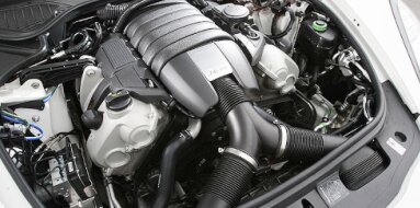
Mercedes-Benz OM601 Specifications
| Engine Model: Mercedes-Benz OM601 |
| Engine Type: 4-cycle inline 4-cylinder SOHC liquid-cooled diesel |
| Total Displacement: 121.9-140.3 cu.in (1.99-2.29 L) |
| Rated Engine Power: 72-79 Hp (53-58 kW) at 4600 rpm |
| Fuel System Type: Indirect injection |
____________________________________________________________________________________
The Mercedes-Benz OM601 is a naturally aspirated
inline-four diesel engine produced between 1983 and 2001, serving as the
successor to the OM615 and OM616 series. Developed as part of a modular engine
family that included the five-cylinder OM602 and six-cylinder OM603, the OM601
introduced significant advancements in diesel powerplant design for
Mercedes-Benz passenger cars and light commercial vehicles.
The engine features a cast-iron cylinder block combined with an aluminum alloy
cylinder head utilizing a single overhead camshaft (SOHC) driven by a duplex
roller chain. This configuration departed from the preceding generation’s
pushrod architecture, enabling improved volumetric efficiency and reduced
mechanical complexity. Two displacement variants were produced: a 2.0-liter
version and a 2.3-liter version. The OM601 gained recognition for its mechanical
simplicity, durability, and ability to achieve extended service intervals well
beyond 1,000,000 km under proper maintenance conditions.
Indirect injection with pre-combustion chambers provided refined operation
compared to earlier diesel engines, while hydraulic valve lifters eliminated the
requirement for manual valve clearance adjustments. Applications spanned the
W201 190 Series, W124 E-Class, W202 C-Class, and multiple commercial vehicle
platforms including the Sprinter and Vito.
OM601 D20 - 2.0L
Displacement: 1,997 cc (121.9 cu.in).
Power Output: 72-75 hp (53-55 kW) @ 4600 rpm.
Torque: 123-126 Nm @ 2700 rpm.
Bore/Stroke: 87 mm x 84 mm.
Compression Ratio: 22:1.
OM601 D23 - 2.3L
Displacement: 2,299 cc (140.3 cu.in).
Power Output: 79 hp (58 kW) @ 3800 rpm.
Torque: 152-157 Nm @ 2300-3000 rpm.
Bore/Stroke: 89 mm x 92.4 mm.
The OM601 engine family operates on a four-stroke Diesel cycle with a
straight-four cylinder configuration. The cylinder numbering follows the
conventional order from the front of the engine to the flywheel end. The firing
order is 1-3-4-2. The valvetrain comprises a single overhead camshaft driven by
a duplex roller chain from the crankshaft, operating two valves per cylinder
through bucket tappets. Hydraulic lash adjusters are integrated into the valve
actuation system, eliminating manual clearance adjustments throughout the engine
service life.
The fuel system utilizes Bosch mechanical injection with an inline injection
pump driven by the camshaft, delivering fuel to pre-combustion chambers located
in the cylinder head. Induction is naturally aspirated across the majority of
production, with a rare turbocharged variant produced for commercial
applications. The engine incorporates a mechanical governor within the injection
pump, enabling operation without electrical power once started. Glow plug
pre-heating is provided for cold start assistance, with a glow plug located in
each pre-combustion chamber.
The cylinder block is constructed from gray cast iron,
providing exceptional rigidity and resistance to thermal distortion under the
high compression ratios characteristic of indirect injection diesel operation.
The block features a deep-skirt design extending below the crankshaft
centerline, contributing to structural stiffness and vibration damping.
Cylinder bores are machined directly into the iron substrate without separate
liners, finished with a plateau honing process to optimize oil retention and
piston ring seating. Bore diameters vary by displacement: the 2.0-liter version
uses an 87.0 mm (3.425 in) bore, while the 2.3-liter version employs an 89.0 mm
(3.504 in) bore. The block incorporates five main bearings with steel-backed,
lead-bronze bearing shells.
Main bearing cap attachment uses four bolts per cap, with the caps constructed
from nodular cast iron for enhanced strength. Coolant passages surround each
cylinder in a full-length water jacket configuration with siamesed bores to
accommodate the cylinder spacing. The block casting includes integrated oil
galleries supplying pressurized lubricant to the crankshaft main bearings,
connecting rod bearings, and the cylinder head via external oil feed pipes.
The cylinder head is manufactured from aluminum-silicon
alloy with a cross-flow design positioning intake ports on the left side and
exhaust ports on the right side of the engine. Combustion chambers are of the
indirect injection configuration, incorporating spherical pre-combustion
chambers offset from the cylinder centerline. Each pre-chamber houses a glow
plug and receives fuel from the injection nozzle positioned at the chamber
inlet.
The SOHC arrangement comprises a single camshaft supported by five bearing caps
machined integrally with the cam carrier. Valve diameters are consistent across
both displacement variants: intake valves measure 42.0 mm (1.654 in) in
diameter, while exhaust valves measure 37.0 mm (1.457 in). Valve stems are 8 mm
(0.315 in) in diameter with chrome-plated surfaces for wear resistance.
Valve seats are sintered metal inserts, with both intake and exhaust seats
employing heat-resistant alloys capable of withstanding the elevated
temperatures of diesel combustion. Valve guides are bronze alloy inserts.
Hydraulic lash adjusters are positioned between the camshaft and valve stems,
maintaining zero valve clearance throughout the operating temperature range. The
camshaft drive system incorporates a duplex roller chain with a hydraulic
tensioner maintaining constant chain tension.
The fuel system operates with a Bosch mechanical inline
injection pump designated MW or M series depending on application. The pump is
driven by the camshaft via a flexible coupling and rotates at half crankshaft
speed. Individual plunger and barrel assemblies supply fuel to each cylinder,
with injection timing adjusted by the pump’s internal camshaft. Injection
pressure ranges between 115 and 130 bar (1,668 and 1,885 psi) depending on
engine speed and load.
The mechanical governor incorporates both idle and maximum speed control
functions, with a lever-operated shut-off mechanism that stops fuel delivery
when the engine is turned off. Fuel injectors are of the nozzle-and-holder type,
with opening pressure set between 115 and 125 bar (1,668 and 1,813 psi). Each
injector mounts into the cylinder head and sprays fuel into the pre-combustion
chamber through a pintle-type nozzle.
The pre-chamber design promotes turbulence and mixing of fuel with air before
combustion proceeds into the main cylinder. A hand primer pump is located on the
fuel filter assembly to facilitate priming after filter changes or fuel system
service. The fuel filter incorporates a water separator with a drain valve at
the lower housing.
The lubrication system is a fully pressurized wet-sump
design incorporating a gear-type oil pump mounted on the crankshaft within the
timing chain cover. The pump draws oil from a stamped steel sump through a
strainer-type pickup. System pressure is regulated by a spring-loaded relief
valve set between 3.0 and 4.5 bar (43.5 and 65.3 psi) depending on engine speed
and temperature. The oil filter is a full-flow spin-on canister type with an
integrated bypass valve set at 2.0 bar (29.0 psi) differential pressure.
An oil-to-water heat exchanger is mounted between the oil filter housing and the
cylinder block, transferring heat from the engine oil to the coolant for rapid
warm-up and temperature stabilization under load. Oil galleries are cast into
the cylinder block and cylinder head, delivering lubricant to the main bearings,
connecting rod bearings, camshaft bearings, and hydraulic lifters. Oil capacity
is 6.0 liters (6.3 qt) including the filter. Recommended oil viscosity ranges
from SAE 10W-40 to 15W-40 meeting Mercedes-Benz specification 228.1 or 228.3 for
diesel applications.
The cooling system operates on a pressurized
closed-loop principle with a belt-driven water pump mounted on the front of the
cylinder block. The pump circulates coolant through the cylinder block water
jacket, cylinder head, and a cross-flow radiator with a belt-driven engine
cooling fan equipped with a viscous clutch. A wax-element thermostat located in
the coolant return housing controls flow to the radiator, with an opening
temperature of 87°C (189°F). System pressure is regulated by a spring-loaded cap
at 1.0 bar (14.5 psi).
Coolant composition is specified as ethylene glycol-based antifreeze mixed with
demineralized water in a 50:50 ratio. The heater circuit draws coolant from the
cylinder head via a dedicated port, passing through the heater core and
returning to the water pump inlet. An expansion tank provides coolant reserve
capacity and allows for thermal expansion. The oil cooler integrated with the
oil filter housing receives coolant from the main circuit, maintaining oil
temperature within a consistent operating range.
Glow plug operation is controlled by a pre-heat relay
and a time control module, with glow plugs reaching operating temperature within
5 to 10 seconds depending on ambient conditions. The exhaust system incorporates
no catalytic converter on early production models, with later versions receiving
oxidation catalysts for emissions compliance.
The vacuum system is extensive, supplying the brake booster, the engine shut-off
actuator, and the transmission vacuum modulator on automatic-equipped vehicles.
A belt-driven vacuum pump mounted on the cylinder head provides the required
negative pressure. The positive crankcase ventilation system routes blow-by
gases from the cylinder head cover to the intake air cleaner through an oil
separator. Engine mounts are rubber-isolated units with hydraulic damping on
later applications.
Length measured from the front of the crankshaft pulley
to the flywheel mounting face is 650 mm (25.59 in). Width across the cylinder
head and injection pump ranges from 580 to 610 mm (22.83 to 24.02 in). Height
from the oil sump mounting flange to the top of the cylinder head cover is 730
mm (28.74 in). The engine dry weight without accessories is 185 kg (408 lb) for
the 2.0-liter variant and 190 kg (419 lb) for the 2.3-liter variant, the mass
reflecting the cast-iron construction.
Oil change intervals are specified at 7,500 km (4,660
mi) or 12 months for earlier production models, extended to 10,000 km (6,214 mi)
for later versions using synthetic lubricants. Fuel filter replacement is
scheduled at 30,000 km (18,641 mi) intervals, with water drain performed every
10,000 km (6,214 mi) or more frequently in humid conditions.
Coolant replacement is recommended every three years or 60,000 km (37,282 mi).
Glow plug replacement intervals are not formally scheduled but inspection is
recommended at 60,000 km (37,282 mi), with replacement as required. Drive belt
inspection is required every 20,000 km (12,427 mi), with replacement every
60,000 km (37,282 mi) for the poly-V belt driving auxiliary components.
Timing chain tensioner inspection is recommended at 100,000 km (62,137 mi), with
replacement if chain noise is evident. Valve clearances require no maintenance
due to the hydraulic lash adjuster system. Injection pump timing should be
verified at 80,000 km (49,710 mi) intervals using a dial gauge indicator.
Injector nozzle replacement is recommended every 100,000 km (62,137 mi).
Cylinder head bolts follow a multi-stage angular
tightening procedure. Initial torque for M12 x 1.5 bolts is 40 Nm (30 lb-ft),
followed by a 60-degree rotation, then a second 60-degree rotation after a
settling period, with a final 30-degree rotation on later production engines.
Main bearing cap bolts for M12 x 1.25 fasteners receive 60 Nm (44 lb-ft) plus 90
degrees.
Connecting rod cap bolts for M10 x 1.0 fasteners are torqued to 30 Nm (22 lb-ft)
plus 90 degrees. Camshaft bearing cap bolts for M8 fasteners receive 20 Nm (15
lb-ft). Intake manifold to cylinder head bolts for M8 fasteners are torqued to
20 Nm (15 lb-ft). Exhaust manifold to cylinder head bolts for M8 fasteners
receive 25 Nm (18 lb-ft). Flywheel to crankshaft bolts for M12 fasteners are
torqued to 100 Nm (74 lb-ft) plus 90 degrees. Crankshaft pulley bolt for M18
fastener receives 300 Nm (221 lb-ft) plus 90 degrees.
Oil filter housing bolts for M8 fasteners are torqued to 25 Nm (18 lb-ft).
Thermostat housing bolts for M6 fasteners receive 9 Nm (80 lb-in). Water pump
mounting bolts for M8 fasteners are torqued to 20 Nm (15 lb-ft). Injection pump
mounting nuts for M10 fasteners receive 25 Nm (18 lb-ft). Injector clamp bolts
for M8 fasteners are torqued to 25 Nm (18 lb-ft). Glow plug torque for M10
threads is 15 Nm (11 lb-ft).
The OM601 engine was installed across a broad range of
Mercedes-Benz passenger cars and commercial vehicles. The W201 190 Series
received the 2.0-liter OM601.912 in the 190 D 2.0 from 1983 to 1991, with the
2.2-liter market designation for North America utilizing the same displacement.
The W124 E-Class received the 2.0-liter OM601.912 in the 200 D from 1985 to
1995. The W202 C-Class was equipped with the 2.0-liter OM601.912 in the C 200 D
from 1993 to 1995.
Commercial applications included the T1 Bremer van series, the Sprinter W901 208
D and 308 D models, and the Vito W638 108 D and 110 D variants. The turbocharged
OM601.970 variant was produced for the Vito 110 TD and Sprinter 210 D
applications, delivering 72 kW (98 hp) with an exhaust gas turbocharger and
increased injection pump calibration. The engine also appeared in the G-Class
W463 200 GE diesel for limited-market production.
____________________________________________________________________________________
| Car Engines Technical Specifications |
| Small Engines Technical Specifications |
| Industrial Engines Technical Specifications |
| Outboard Engines Technical Specifications |