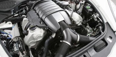
Mercedes-Benz M282 Specifications
| Engine Model: Mercedes-Benz M282 |
| Engine Type: 4-cycle 4-cylinder DOHC 16-valve turbocharged liquid-cooled gasoline |
| Total Displacement: 81.3 cu.in (1.33 L) |
| Rated Engine Power: 107-161 Hp (80-120 kW) at 6500 rpm |
| Fuel System Type: Gasoline direct injection |
____________________________________________________________________________________
The Mercedes-Benz M282 is a 1.3-liter turbocharged
inline-four engine introduced in 2018 as part of the second-generation M282
family, developed in cooperation with the Renault-Nissan-Mitsubishi Alliance
where it is designated as the H5HT or HR13DDT. This engine was engineered to
replace the 1.6-liter M270, delivering reduced displacement while maintaining or
exceeding power output through advanced turbocharging and high-pressure direct
injection. The M282 was designed explicitly for transverse mounting in
Mercedes-Benz’s compact vehicle architecture, serving as the foundational
powertrain for the A-Class, B-Class, CLA, GLA, and GLB model families.
The engine’s development prioritized compactness, thermal efficiency, and
emissions compliance with the Euro 6d-TEMP standard. Its architecture centers on
a die-cast aluminum cylinder block treated with NANOSLIDE coating, a technology
derived from AMG V8 engines that reduces internal friction and wear. The
cylinder head employs a distinctive delta-shaped design - narrower and taller
than conventional configurations - which enabled the integration of intake and
exhaust manifolds into a compact package.
A notable innovation introduced on higher-output variants is cylinder
deactivation, a system that selectively shuts down cylinders two and three under
partial load to reduce fuel consumption without compromising refinement. The
M282’s power output spans multiple calibration levels, from 107 hp in
entry-level applications to 161 hp in the 200 variants, with a consistent torque
plateau optimized for urban and highway driving conditions.
Engine Type: Inline 4-cylinder, 4-cycle, turbocharged, water-cooled.
Displacement: 1,332 cc (81.3 cu.in).
Bore: 72.2 mm (2.84 in).
Stroke: 81.4 mm (3.20 in).
Compression Ratio: 10.6:1.
Valvetrain Configuration: Dual Overhead Camshaft, 16 valves (4 valves per
cylinder).
Continuous variable valve timing on intake and exhaust camshafts.
Firing Order: 1-3-4-2.
Maximum Power (160 variant): 80 kW (107 hp) @ 5,500-6,500 rpm.
Maximum Power (180 variant): 100 kW (134 hp) @ 5,500-6,500 rpm.
Maximum Power (200 variant): 120 kW (161 hp) @ 5,500-6,500 rpm.
Maximum Torque (160 variant): 180 Nm (133 lb-ft) @ 1,750-4,000 rpm.
Maximum Torque (180 variant): 200 Nm (148 lb-ft) @ 1,750-4,000 rpm.
Maximum Torque (200 variant): 250 Nm (184 lb-ft) @ 1,750-4,000 rpm.
Redline: 6,500 rpm with fuel cutoff at 6,800 rpm.
The cylinder block is manufactured from die-cast
aluminum alloy using a high-pressure casting process. This material selection
reduces overall engine mass to approximately 110 kg (242 lb) fully dressed,
contributing to favorable vehicle weight distribution and reduced front-axle
loading in transverse applications. The open-deck design incorporates NANOSLIDE
cylinder bore coating, a process involving the high-velocity application of an
iron-carbon alloy layer directly onto the aluminum bore surfaces.
Following coating application, the bores undergo a precision honing process that
yields a mirror-like surface finish with embedded hard particles, reducing
friction by approximately 50 percent compared to conventional cast iron liners
while enhancing heat transfer from the combustion chamber to the cooling system.
Bore diameter measures 72.2 mm (2.84 in) with a piston stroke of 81.4 mm (3.20
in), yielding a total displacement of 1,332 cc (81.3 cu.in). This under-square
configuration favors mid-range torque generation while maintaining high-rpm
capability. The cylinder block incorporates a deep-skirt design extending below
the crankshaft centerline, providing enhanced lateral rigidity and reducing
vibration transmission to the vehicle structure.
The crankshaft is manufactured from forged micro-alloy steel with
induction-hardened journal surfaces. Main bearing journal diameter measures 48.0
mm (1.89 in), and connecting rod journal diameter measures 42.0 mm (1.65 in).
Five main bearings support the crankshaft, with thrust washers positioned at the
center main bearing to control axial play. Connecting rods are manufactured from
forged high-carbon steel with a fracture-split big end design for precise cap
alignment and consistent bearing crush. Pistons are cast aluminum with a
low-friction skirt coating and a reinforced ring land area to withstand the
elevated cylinder pressures generated by turbocharging.
The cylinder head is manufactured from aluminum alloy
utilizing a delta-shaped design - a configuration where the head is narrower and
taller than conventional designs. This architecture enabled the integration of
intake and exhaust manifold functions into the head casting, reducing overall
engine width and eliminating external manifold components.
The intake ports are integrated into the upper portion of the head, while the
exhaust ports are partially integrated into the lower portion, allowing the
turbocharger to be mounted directly to the cylinder head without an intermediate
exhaust manifold.
Each cylinder head contains 16 valves: eight intake valves and eight exhaust
valves. Intake valve diameter measures 30.0 mm (1.18 in), while exhaust valve
diameter measures 26.0 mm (1.02 in). Valve stem diameter is 5.0 mm (0.20 in) for
both intake and exhaust. Exhaust valves are hollow and sodium-filled to enhance
heat transfer from the valve head to the valve guide, a necessity given the
compact packaging and elevated exhaust gas temperatures.
The valvetrain is driven by a silent-type timing chain with a pitch of 8.0 mm
(0.31 in). The chain routes from the crankshaft sprocket to the exhaust camshaft
sprocket, with a second chain segment connecting the exhaust camshaft to the
intake camshaft. An automatic hydraulic tensioner, supplied with engine oil
pressure, maintains consistent chain tension throughout the engine’s service
life. The timing chain is designed for the life of the engine under normal
operating conditions.
Continuous variable valve timing (VVT) is applied to both intake and exhaust
camshafts. Camshaft phasers utilize hydraulic actuation controlled by solenoid
valves, with an adjustment range of 60 degrees crankshaft angle on the intake
side and 40 degrees on the exhaust side. This system enables optimization of
volumetric efficiency across the engine speed range, as well as internal exhaust
gas recirculation for emissions reduction.
Cylinder deactivation is implemented on 200 variants. Adjustable camshaft
segments on cylinders two and three incorporate electromechanical switching
elements that shift the cam profile from a high-lift profile to a zero-lift
profile under partial-load conditions.
When deactivated, the intake and exhaust valves remain closed, and fuel
injection ceases on those cylinders. The system operates between 1,250 and 3,800
rpm, transitioning between four-cylinder and two-cylinder operation within 20
milliseconds. Activation is imperceptible to occupants due to active engine
mount countermeasures. Valve clearance is maintained via hydraulic lash
adjusters integrated into the cylinder head casting. Roller finger followers
reduce friction at the cam-to-valve interface.
The M282 employs a third-generation direct injection
system operating at high pressure. Fuel is delivered via a two-stage system: a
low-pressure pump within the fuel tank supplies fuel at 4.0-6.0 bar (58-87 psi)
to a high-pressure pump mounted on the cylinder head. The high-pressure pump is
a single-piston, quantity-controlled unit driven by a cam lobe on the intake
camshaft.
Fuel rail pressure is regulated up to 250 bar (3,625 psi) under high-load
conditions, with pressure modulated by the engine control unit based on load and
engine speed. The injectors are solenoid-actuated units with six-hole nozzles
designed to produce a finely atomized spray pattern.
Injectors are mounted centrally within the cylinder head, directing fuel
directly into the combustion chamber. Multiple injection events per combustion
cycle - including pilot injection, main injection, and post-injection - are
utilized to reduce combustion noise and enable particulate filter regeneration.
The engine management system utilizes a 32-bit Bosch ECU (MED 17) operating in
closed-loop control. Inputs include a hot-film mass airflow sensor, camshaft
position sensors, crankshaft position sensor, engine coolant temperature sensor,
intake air temperature sensor, charge air temperature sensor, and wideband
oxygen sensors positioned before and after the catalytic converter.
The lubrication system utilizes a variable-displacement
vane-type oil pump mounted to the front of the crankshaft. The pump incorporates
a control valve that adjusts displacement based on engine speed, load, and oil
temperature, reducing parasitic losses by providing only the oil flow required
for current operating conditions. Maximum oil pressure is regulated to 4.5-5.5
bar (65-80 psi).
Total oil capacity including filter is 5.2-5.5 liters (5.5-5.8 qt). Recommended
oil viscosity is 0W-20 meeting Mercedes-Benz specification MB 229.71, or 5W-30
meeting MB 229.52 for applications requiring higher viscosity. These
low-viscosity formulations are specified to reduce internal friction and improve
cold-start fuel economy. Oil pressure specifications require a minimum of 1.0
bar (15 psi) at warm idle and 2.5-3.5 bar (36-51 psi) at 3,000 rpm.
An air-oil separator is integrated into the valve cover, utilizing a cyclonic
separation system to minimize oil carryover into the intake system. The oil
cooler is a liquid-to-oil plate-type heat exchanger mounted to the oil filter
housing, utilizing engine coolant to stabilize oil temperature.
The cooling system is pressurized and utilizes a
centrifugal water pump driven by the accessory drive belt. The pump features a
cast aluminum housing and a composite impeller. An electric auxiliary water pump
is incorporated to maintain coolant circulation through the turbocharger housing
after engine shutdown, preventing localized boiling and thermal damage to
bearing assemblies.
Thermostat type is a wax-pellet unit integrated into the coolant outlet housing.
Opening temperature is 88-92 °C (190-198 °F). The system incorporates a
map-controlled coolant valve that can restrict flow to the radiator during
warm-up to accelerate engine heating.
Total coolant capacity ranges from 7.5-8.5 liters (7.9-9.0 qt), inclusive of the
engine block, radiator, heater core, charge air cooler, and oil cooler circuits.
The cooling system is divided into a high-temperature circuit for the engine and
a low-temperature circuit for the charge air cooler. System pressure is
controlled by a radiator cap rated at 1.4 bar (20 psi).
Aspiration System: The M282 employs a single
twin-scroll turbocharger mounted directly to the cylinder head, eliminating a
separate exhaust manifold. The turbine housing incorporates a twin-scroll inlet
that separates exhaust pulses from cylinders one and four from those of
cylinders two and three, minimizing interference and improving transient
response. An electronically controlled wastegate actuator provides precise boost
pressure regulation across the operating range. Maximum boost pressure ranges
from 1.4-1.8 bar (20-26 psi) absolute depending on engine variant. Charge air is
routed through an air-to-water charge air cooler integrated into the intake
manifold, followed by an electronically controlled throttle body with a bore
diameter of 52 mm (2.05 in).
Timing System: The timing chain system incorporates a primary chain driving the
exhaust camshaft and a secondary chain between camshafts. Chain guides are
manufactured from low-friction polymer materials. The hydraulic tensioner is
supplied with filtered engine oil through a dedicated gallery.
Exhaust Aftertreatment: The engine is equipped with a close-coupled catalytic
converter positioned immediately downstream of the turbocharger outlet to
achieve rapid light-off during cold starts. An Otto particulate filter (OPF) is
integrated into the exhaust system downstream of the catalytic converter,
utilizing a ceramic substrate with alternating inlet and outlet channels to
capture particulate matter. Regeneration occurs passively under normal driving
conditions and actively via post-injection events when required. Two oxygen
sensors are employed: a wideband air-fuel ratio sensor upstream of the catalytic
converter and a switching-type oxygen sensor downstream for catalyst and filter
monitoring.
Engine Management: The Ecu.integrates control of fuel injection, ignition
timing, boost pressure, wastegate position, variable valve timing, cylinder
deactivation, thermostat operation, and cooling fan speed. Ignition system
utilizes direct-acting ignition coils mounted over each spark plug
(coil-on-plug). Spark plug type is iridium-tipped with a gap of 0.7 mm (0.028
in).
Crankcase Ventilation: A closed-loop system routes blow-by gases from the valve
cover through an integrated oil separator, returning condensed oil to the sump
while directing vapor to the intake system upstream of the turbocharger
compressor inlet.
Overall Length: 580 mm (22.8 in) measured from
accessory drive pulley face to transmission mounting flange.
Overall Width: 620 mm (24.4 in) inclusive of the turbocharger assembly and
intake system.
Overall Height: 670 mm (26.4 in) from oil pan bottom surface to valve cover top
surface.
Dry Weight: 110-115 kg (242-254 lb) depending on accessory equipment and
cylinder deactivation hardware.
Timing Chain: Designed for engine life under normal
operating conditions. Inspection recommended at 160,000 km (100,000 mi). Chain
stretch measured by camshaft phaser position relative to ECU reference values.
Spark Plug Replacement Interval: 50,000 km (31,000 mi) for iridium-tipped plugs.
Engine Oil Change Interval: 15,000 km (9,300 mi) or 12 months, as determined by
the flexible service system (ASSYST). Maximum interval reduced to 10,000 km
(6,200 mi) for severe service conditions including frequent short trips,
sustained high-load operation, or dusty environments. Oil Filter Replacement
Interval: Replace with every oil change. Air Filter Element Replacement
Interval: 45,000 km (28,000 mi) or as indicated by the maintenance system.
Fuel Filter Replacement Interval: The in-tank filter is part of the fuel pump
module and is not a scheduled maintenance item. Replacement indicated only upon
pump failure or contamination. Coolant Change Interval: 120,000 km (75,000 mi)
or 8 years. Drive Belt (accessory) Replacement Interval: 60,000 km (37,000 mi)
or when cracking, glazing, or wear is observed.
Inspection interval: 40,000 km (25,000 mi). Idle Speed (warm, neutral): 700-800
rpm, controlled by ECU. Fuel Pressure (high-pressure system): 40-250 bar
(580-3,625 psi) regulated by ECU. Compression Pressure: Minimum 11.0 bar (160
psi) with no cylinder varying more than 2.0 bar (29 psi) from others. Measured
with engine warm, throttle fully open.
Cylinder Head Bolts (cold), Step 1: 30 Nm (22 lb-ft).
Cylinder Head Bolts (cold), Step 2: 60 Nm (44 lb-ft) plus 90° rotation.
Crankshaft Damper Pulley Bolt: 150-160 Nm (111-118 lb-ft) plus 90° rotation.
Connecting Rod Cap Bolts: 25-30 Nm (18-22 lb-ft) plus 90° rotation.
Main Bearing Cap Bolts, Step 1: 30 Nm (22 lb-ft).
Main Bearing Cap Bolts, Step 2: 60 Nm (44 lb-ft) plus 90° rotation.
Flywheel / Drive Plate Bolts: 80-90 Nm (59-66 lb-ft) plus 90° rotation.
Camshaft Bearing Cap Bolts: 20-24 Nm (15-18 lb-ft).
Camshaft Sprocket Bolts: 70-80 Nm (52-59 lb-ft).
Valve Cover Bolts: 8-10 Nm (6-7 lb-ft).
Intake Manifold Bolts: 18-22 Nm (13-16 lb-ft).
Exhaust Manifold Nuts (turbocharger to head): 25-30 Nm (18-22 lb-ft).
Turbocharger Support Bracket: 20-25 Nm (15-18 lb-ft).
Oil Pan Bolts: 8-12 Nm (6-9 lb-ft) for M6 fasteners.
Oil Pan Bolts: 20-25 Nm (15-18 lb-ft) for M8 fasteners.
Timing Chain Tensioner: 40-45 Nm (30-33 lb-ft).
High-Pressure Fuel Pump Mounting Bolts: 15-20 Nm (11-15 lb-ft).
Fuel Injector Clamp Bolts: 25-30 Nm (18-22 lb-ft).
Spark Plugs: 23-28 Nm (17-21 lb-ft).
Water Pump Mounting Bolts: 10-12 Nm (7-9 lb-ft).
Thermostat Housing Bolts: 9-11 Nm (7-8 lb-ft).
Crankshaft Position Sensor Mounting Bolt: 8-10 Nm (6-7 lb-ft).
Knock Sensor: 20-25 Nm (15-18 lb-ft).
A-Class (W177): 2018-present. The M282 was installed
across the A-Class hatchback and sedan lineup in A 160, A 180, and A 200
designations. The A 250e plug-in hybrid variant utilized the M282 in combination
with an electric motor, with the engine calibrated for Atkinson-cycle operation
to optimize efficiency in hybrid applications.
B-Class (W247): 2019-present. The M282 served as the core powertrain for the
B-Class compact MPV, available in B 160, B 180, and B 200 variants, as well as
the B 250e plug-in hybrid.
CLA-Class (C118): 2019-present. The four-door coupe received the M282 in CLA 180
and CLA 200 configurations, with the CLA 250e hybrid variant utilizing the
engine in the plug-in hybrid powertrain.
GLA-Class (H247): 2020-present. The compact crossover SUV was equipped with the
M282 in GLA 180 and GLA 200 variants, as well as the GLA 250e plug-in hybrid.
GLB-Class (X247): 2020-present. The seven-seat compact SUV received the M282 in
GLB 180 and GLB 200 variants, with the GLB 250e hybrid variant available in
select markets.
Renault and Alliance Applications: The M282 engine architecture, designated as
H5HT or HR13DDT, was utilized across Renault Megane, Kadjar, and Arkana models,
as well as Nissan Qashqai and Dacia Duster applications, reflecting the
cooperative development arrangement between Mercedes-Benz and the
Renault-Nissan-Mitsubishi Alliance.
____________________________________________________________________________________
| Car Engines Technical Specifications |
| Small Engines Technical Specifications |
| Industrial Engines Technical Specifications |
| Outboard Engines Technical Specifications |