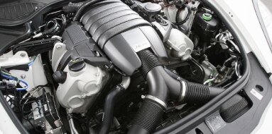
Subaru EJ201 Specifications
| Engine Model: Subaru EJ201 |
| Engine Type: 4-cycle 4-cylinder SOHC 16-valve liquid-cooled gasoline |
| Total Displacement: 121.6 cu.in (1.99 L) |
| Rated Engine Power: 125 Hp (92 kW) at 5600 rpm |
| Fuel System Type: Multi-point electronic fuel injection |
____________________________________________________________________________________
The Subaru EJ201 is a 2.0-liter, naturally aspirated
flat-four gasoline engine produced from the late 1990s through the mid-2000s,
representing the Phase II evolution of Subaru’s venerable EJ20 series.
Engineered as a replacement for the Phase I EJ20E, the EJ201 was developed with
a focus on improved low-end torque, enhanced fuel efficiency, and reduced
emissions, aligning with the demands of global markets where Subaru’s compact
cars and crossovers gained increasing popularity. The engine retains Subaru’s
characteristic horizontally opposed configuration, with aluminum alloy
construction for both the cylinder block and cylinder heads.
The Phase II architecture introduced several significant refinements, including
a relocated crankshaft thrust bearing, a redesigned intake manifold, and a
revised cylinder head design that improved port flow characteristics. The EJ201
became a widely deployed power unit across Subaru’s Impreza, Legacy, and
Forester ranges in Europe, Australia, Japan, and other markets, valued for its
smooth operation, compact packaging, and dependable performance in daily-driving
applications.
The Subaru EJ201 is a four-stroke, water-cooled, horizontally opposed
four-cylinder gasoline engine with a total displacement of 1,994 cc (121.6
cu.in). The bore and stroke dimensions are 92.0 mm and 75.0 mm, respectively,
creating an oversquare configuration that favors high-rpm power delivery while
maintaining a compact engine height - a key advantage of the flat-four layout.
The valvetrain employs a single overhead camshaft (SOHC) design per cylinder
bank, with four valves per cylinder - two intake and two exhaust - for a total
of 16 valves. Each cylinder head houses a single camshaft driven by the timing
belt, with valve actuation provided by rocker arms that convert cam lobe motion
to valve opening.
The fuel system utilizes multi-point fuel injection (MPFI) managed by an engine
control unit that employs a manifold absolute pressure (MAP) sensor for load
detection, replacing the mass airflow (MAF) sensor used in earlier Phase I
engines. Induction is naturally aspirated through a cast aluminum intake
manifold with tuned runner lengths optimized for mid-range torque.
The compression ratio is set at 10.1:1, a value selected to balance power output
with compatibility with standard-grade petrol. Maximum power is rated at 92 kW
(125 hp) at 5,600 rpm. Maximum torque is produced at 3,600 rpm, with a rating of
184 Nm (136 lb-ft). The engine speed limiter is set at approximately 6,500 rpm.
The firing order is 1-3-2-4, a configuration specific to Subaru’s flat-four
engines that provides balanced primary and secondary forces owing to the
horizontally opposed layout.
The cylinder block is manufactured from aluminum alloy
with cast iron cylinder liners, a construction that reduces overall engine mass
while providing a durable wear surface for the pistons and piston rings. The
horizontally opposed configuration positions the cylinders in two banks arrayed
at 180 degrees, resulting in a low center of gravity and inherently balanced
operation. The block utilizes an open-deck design, where the cylinder bores are
open at the top deck surface, allowing efficient coolant flow around the upper
cylinder region. This design provides excellent cooling for daily-driving
applications but limits structural rigidity for high-boost forced induction
modifications.
The Phase II architecture relocates the crankshaft thrust bearing to the fifth
main bearing position (the rear-most bearing), a change from the Phase I design
where the thrust bearing was positioned at the third main bearing. This
relocation improves crankshaft stability and reduces thrust face wear under
sustained clutch operation. The crankshaft is a forged steel unit with eight
counterweights, supported by five main bearings.
The connecting rods are constructed from sintered metal or forged steel
depending on the production year. Cylinder bores are precision-machined with a
plateau honed finish to optimize oil retention and piston ring sealing. The
block incorporates a water jacket that surrounds the cylinders for effective
heat transfer, with coolant flow directed upward toward the cylinder heads.
Two separate cylinder heads, one for each bank, are
manufactured from aluminum alloy and feature a single overhead camshaft (SOHC)
arrangement. Each cylinder head houses one camshaft supported by five bearing
journals, driven by the timing belt through a sprocket on the front of the
camshaft. The Phase II cylinder head design incorporates revised intake port
geometry and combustion chamber shape compared to earlier Phase I heads,
improving charge motion and combustion efficiency.
Valves are arranged with two intake and two exhaust valves per cylinder,
actuated by rocker arms that pivot on a rocker shaft. Intake valves measure 33.0
mm (1.30 in) in diameter, while exhaust valves measure 28.0 mm (1.10 in) in
diameter. Unlike earlier EJ engines that utilized hydraulic lash adjusters, the
EJ201 employs screw-and-locknut mechanical valve adjusters. The valve clearance
is set by adjusting a threaded tappet screw on the rocker arm, with the locknut
securing the adjustment.
This design requires periodic valve clearance inspection and adjustment but
provides precise control over valvetrain geometry. The valve springs are of the
single-coil type with sufficient spring force to maintain valve control to the
engine speed limit. The combustion chamber is of the compact pent-roof design
with centrally located spark plugs to optimize flame propagation. The cylinder
head gasket is a multi-layer steel (MLS) design, providing reliable sealing
between the aluminum heads and aluminum block under varying thermal loads.
The fuel system is a multi-point electronic fuel
injection (MPFI) system operating at conventional port injection pressures. An
electric fuel pump mounted within the fuel tank delivers fuel through a
replaceable filter to a fuel rail mounted on the intake manifold. The fuel
pressure regulator maintains a constant pressure across the injectors,
referenced to intake manifold vacuum to maintain a consistent pressure
differential. The fuel injectors are solenoid-actuated, with flow rates
calibrated to the engine’s power output.
The engine control unit (ECU) employs a manifold absolute pressure (MAP) sensor
for load detection, a departure from the mass airflow (MAF) sensors used in
Phase I engines. The MAP-based system is less susceptible to contamination and
provides more reliable operation over the engine’s service life.
The ECU calculates injector pulse width based
on inputs from the MAP sensor, throttle position sensor, coolant
temperature sensor, intake air temperature sensor, crankshaft position
sensor, camshaft position sensors, and heated oxygen sensor. The system
employs closed-loop fuel control during part-throttle operation,
adjusting fuel delivery based on oxygen sensor feedback to maintain a
stoichiometric air-fuel ratio for optimal catalytic converter
efficiency.
The lubrication system is a full-flow, pressurized
circuit utilizing a gear-type oil pump mounted within the front timing case and
driven directly by the crankshaft. The pump draws engine oil from a baffled
aluminum sump through a strainer screen before directing it through a full-flow
spin-on oil filter. An oil pressure relief valve maintains system pressure
within the specified range, with operating pressure at operating speed between
3.0 bar (44 psi) and 4.5 bar (65 psi).
The main oil gallery distributes pressurized oil to the crankshaft main
bearings, connecting rod bearings, camshaft bearings, and rocker arm assemblies.
The horizontal orientation of the engine requires careful oil drainback design
to ensure adequate oil return to the sump. The total engine oil capacity,
including the filter, is 4.5 L (4.8 qt). Recommended oil viscosity is 5W-30,
5W-40, or 10W-40 with a high-quality synthetic or semi-synthetic formulation.
The cooling system operates as a pressurized,
thermostatically controlled water circulation circuit. A belt-driven centrifugal
water pump, mounted to the front of the cylinder block, circulates a mixture of
water and ethylene glycol antifreeze through the cylinder block, cylinder heads,
and the main radiator. The Phase II engine features a bolted-on water pump
design, replacing the pressed-in pump used in Phase I engines, which simplifies
replacement and reduces the risk of coolant leaks. The thermostat is a
wax-pellet type positioned on the coolant outlet of the engine, maintaining
operating temperature within the range of 85°C to 95°C (185°F to 203°F).
The radiator is a cross-flow aluminum construction with plastic end tanks. An
electric cooling fan, controlled by the engine control unit based on coolant
temperature, provides forced airflow during low-speed operation or high ambient
temperatures. An expansion tank allows for coolant expansion and provides a
point for air separation from the system. The total cooling system capacity
varies by chassis but is 6.0 L (6.3 qt) to 6.5 L (6.9 qt) for the complete
system.
Intake System: The intake manifold is constructed from
aluminum and is specific to the Phase II architecture, with revised runner
lengths and plenum volume compared to Phase I designs. The manifold incorporates
a resonance chamber to reduce intake noise and optimize cylinder filling across
the engine speed range. The air intake system includes a dry-type paper air
filter housed in a large-capacity air cleaner assembly.
Exhaust System: The exhaust manifolds are constructed from tubular steel, with
one manifold per cylinder bank merging into a single exhaust pipe downstream. A
heated oxygen sensor is mounted in the exhaust system upstream of the catalytic
converter to provide feedback to the ECU for closed-loop fuel control. The
exhaust system includes a three-way catalytic converter to comply with emissions
regulations.
Ignition System: The ignition system utilizes a distributorless ignition system
with individual ignition coils mounted directly over each spark plug in later
models, or a wasted-spark configuration with dual coils in earlier versions. The
engine control unit determines ignition timing based on inputs from the
crankshaft position sensor, camshaft position sensors, and knock sensor. The
knock sensor allows the ECU to retard ignition timing under detonation
conditions to protect the engine while optimizing timing for maximum power and
efficiency under normal conditions.
Timing Drive: The camshafts are driven by a toothed rubber timing belt. The belt
also drives the water pump in this configuration. This is an interference engine
design; failure of the timing belt results in piston-to-valve contact, causing
catastrophic engine damage.
The EJ201’s horizontally opposed configuration results
in a low-profile engine with compact height dimensions. The overall length,
measured from the front accessory drive to the flywheel mating face, is 650 mm
(25.6 in). Width across the cylinder heads and intake manifold is 850 mm (33.5
in), reflecting the opposed cylinder layout. Height from the bottom of the oil
sump to the top of the intake manifold is 600 mm (23.6 in). The dry weight of
the engine, inclusive of the intake and exhaust manifolds, alternator, starter
motor, and fuel system components but without transmission or fluids, is 140 kg
(309 lb).
The EJ201 requires routine maintenance to ensure
longevity, with several service items specific to the Phase II architecture. The
engine oil and filter must be replaced at intervals not exceeding 10,000 km
(6,214 mi) or 12 months under normal operation. The timing belt is a critical
maintenance item with a replacement interval of 100,000 km (62,137 mi) for most
markets. Due to the interference design, the timing belt tensioner, idler
pulleys, and water pump must be replaced concurrently.
Valve clearance adjustment is required at intervals of 60,000 km (37,282 mi) to
100,000 km (62,137 mi), with the cold clearance specification of 0.20 mm (0.008
in) to 0.25 mm (0.010 in) for intake valves and 0.25 mm (0.010 in) to 0.30 mm
(0.012 in) for exhaust valves. The spark plugs require replacement every 60,000
km (37,282 mi) for platinum-tipped variants.
The air filter element should be inspected at each oil change and replaced every
30,000 km (18,641 mi) to 40,000 km (24,855 mi) depending on operating
conditions. The fuel filter is a replaceable in-line unit with a recommended
service interval of 40,000 km (24,855 mi). Coolant replacement is specified at
60,000 km (37,282 mi) or every three years.
Cylinder Head Bolts: 30 Nm (22 lb-ft).
Main Bearing Cap Bolts: 30 Nm (22 lb-ft).
Connecting Rod Cap Bolts: 25 Nm (18 lb-ft).
Camshaft Bearing Caps: 10 Nm (7 lb-ft).
Flywheel Bolts: 70 Nm (52 lb-ft).
Crankshaft Pulley Bolt: 150 Nm (111 lb-ft).
Intake Manifold Bolts: 20 Nm (15 lb-ft).
Exhaust Manifold Nuts: 25 Nm (18 lb-ft).
Oil Pan Bolts: 10 Nm (7 lb-ft).
Timing Belt Tensioner Bolt: 25 Nm (18 lb-ft).
Spark Plugs: 25 Nm (18 lb-ft).
Engine Mounting Brackets: 40 Nm (30 lb-ft).
The Subaru EJ201 engine was deployed across Subaru’s
core model ranges in Europe, Australia, Japan, and other markets from the late
1990s through the mid-2000s, serving as the base naturally aspirated power unit.
Subaru Impreza (GC8 / GF8, 1998-2000): The EJ201 was installed in the
first-generation Impreza as the base engine for the 2.0-liter models, replacing
the earlier EJ20E. Available in both sedan (GC8) and wagon (GF8) body styles,
this application represented the entry point to the Impreza range in markets
where the 2.0-liter displacement was preferred over the larger 2.2-liter or
2.5-liter engines.
Subaru Impreza (GD1 / GG1, 2000-2005): The engine was carried over into the
second-generation Impreza, continuing as the base 2.0-liter power unit for the
GD1 sedan and GG1 wagon models. This generation saw the EJ201 offered across a
wide range of European and Australian market trims.
Subaru Legacy / Liberty (BE5 / BH5, 1998-2003): The EJ201 served as the
entry-level engine for the third-generation Legacy, marketed as the Liberty in
Australia. Installed in both sedan (BE5) and wagon (BH5) body styles, the engine
provided dependable performance in Subaru’s mid-size offering.
Subaru Forester (SF5, 1998-2002): The EJ201 was utilized in the first-generation
Forester as the base 2.0-liter engine, offering a balance of power and fuel
efficiency in Subaru’s compact crossover SUV.
____________________________________________________________________________________
| Car Engines Technical Specifications |
| Small Engines Technical Specifications |
| Industrial Engines Technical Specifications |
| Outboard Engines Technical Specifications |