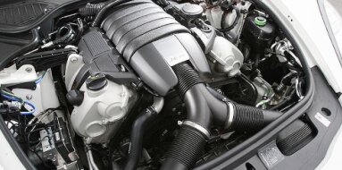
Suzuki G13BB Specifications
| Engine Model: Suzuki G13BB |
| Engine Type: 4-cycle inline 4-cylinder SOHC 16-valve liquid-cooled gasoline |
| Total Displacement: 79.2 cu.in (1.29 L) |
| Rated Engine Power: 80-86 Hp (60-63 kW) at 6000 rpm |
| Fuel System Type: Multi-point fuel injection |
____________________________________________________________________________________
The Suzuki G13BB is a 1.3-liter inline-four gasoline
engine representing the advanced evolution of the G13 engine family, produced
from the mid-1990s through the early 2000s. This powerplant distinguished itself
through the adoption of a 16-valve SOHC cylinder head and electronic multi-point
fuel injection (MPFI), marking a significant departure from the carbureted
8-valve G13A and G13B variants that preceded it.
The G13BB was engineered to deliver improved power output, enhanced fuel
efficiency, and reduced emissions while maintaining the compact dimensions and
lightweight construction that made the G13 family a preferred choice for
Suzuki’s small passenger cars and light off-road vehicles.
The engine’s architecture reflected Suzuki’s focus on mass reduction and
packaging efficiency. The all-aluminum construction - cylinder block and
cylinder head both manufactured from aluminum alloy - reduced engine mass
substantially compared to cast iron equivalents, contributing to the favorable
power-to-weight ratios of vehicles such as the Suzuki Jimny and Swift.
The SOHC valvetrain operated 16 valves through a timing belt drive, with a
distributorless ignition system providing precise spark control. The G13BB
became the standard 1.3-liter powertrain for a wide range of Suzuki global
products and was also produced under license by Maruti Suzuki in India for the
Gypsy King and other domestic market vehicles.
The G13BB is a four-stroke, water-cooled, naturally aspirated gasoline engine
configured for longitudinal or transverse mounting depending on vehicle
application. The engine utilizes multi-point fuel injection and a
distributorless ignition system.
Engine Type: Inline-4, 4-cycle, water-cooled, naturally aspirated
Displacement: 1,298 cc (79.2 cu.in)
Bore: 74.0 mm (2.91 in)
Stroke: 75.5 mm (2.97 in)
Compression Ratio: 9.5:1
Firing Order: 1-3-4-2
Valvetrain: SOHC, 16-valve (4 valves per cylinder)
Maximum Power: 60-63 kW (80-86 hp) at 6,000 rpm
Maximum Torque: 103-115 Nm (76-85 lb-ft) at 3,000-4,500 rpm
Redline: 6,500 rpm
Engine Management: Suzuki electronic control unit with MPFI
The cylinder block is manufactured from aluminum alloy
using a high-pressure die-casting process, a material selection that
significantly reduces engine mass compared to cast iron alternatives. The block
features an open-deck design where the cylinder bores are supported at the top
only by the water jacket perimeter, enhancing cooling efficiency around the
upper cylinder area while minimizing casting complexity.
Cast-in-place iron cylinder liners are inserted during the casting process,
providing a durable wear surface compatible with the aluminum piston assemblies.
The liners are machined with a plateau-honed finish that promotes ring sealing
and oil retention. The block incorporates a siamesed bore configuration where
adjacent cylinders share common walls, reducing overall engine length and
increasing structural rigidity.
The crankcase incorporates a deep-skirt design with the block casting extending
below the crankshaft centerline. The main bearing caps are manufactured from
cast iron and secured with two bolts per cap. The block includes mounting
provisions for the oil filter, oil pressure switch, and coolant passages. A
stamped steel or cast aluminum oil pan is bolted to the lower crankcase.
Block Material: Aluminum alloy with cast iron cylinder liners
Bore Diameter: 74.0 mm (2.91 in)
Cylinder Configuration: Inline, open-deck, siamesed bores
Main Bearing Quantity: 5
Main Bearing Cap Design: Cast iron, two-bolt attachment
The cylinder head is constructed from aluminum alloy
using a permanent mold casting process, selected for its thermal conductivity
and reduced mass. The cross-flow port configuration places intake ports on one
side and exhaust ports on the opposite side. The SOHC valvetrain operates 16
valves - four per cylinder - via rocker arms that pivot on a single rocker
shaft.
The camshaft is supported in bearing journals machined directly into the
cylinder head casting, with bearing caps of identical construction. Valve
actuation is accomplished via roller-type rocker arms or conventional sliding
rocker arms depending on production variant, with the rocker arms incorporating
adjusting screws for manual valve clearance adjustment. The combustion chambers
are of a pent-roof design with centrally located spark plugs, and four valves
per cylinder arranged in a compact pattern promoting efficient flame
propagation.
The cylinder head incorporates pressed-in valve seat inserts, with exhaust seats
manufactured from a heat-resistant nickel-based alloy. Valve guides are pressed
into the head and machined to precise internal diameters. The intake ports are
designed to generate swirl within the combustion chamber, improving air-fuel
mixing and combustion efficiency.
Head Material: Aluminum alloy
Valve Configuration: SOHC, 16-valve (4 valves per cylinder)
Intake Valve Diameter: 30.0 mm (1.18 in)
Exhaust Valve Diameter: 25.0 mm (0.98 in)
Valve Stem Diameter: 6.0 mm (0.24 in)
Valve Seat Angle: 45 degrees
Camshaft Drive: Timing belt with automatic tensioner
Valve Clearance (Cold, Intake): 0.13-0.17 mm (0.005-0.007 in)
Valve Clearance (Cold, Exhaust): 0.23-0.27 mm (0.009-0.011 in)
Interference Engine: Yes - valve-to-piston contact occurs if timing belt fails
The fuel system employs electronic multi-point fuel
injection (MPFI) with individual injectors positioned in the intake manifold
runners. This system replaced the carbureted and single-point injection
configurations used on earlier G13 variants, providing improved fuel
atomization, more precise air-fuel ratio control, and enhanced cold-start
performance.
An in-tank electric fuel pump supplies fuel to the engine at regulated pressure.
The fuel pressure regulator is mounted on the fuel rail or integrated with the
fuel pump module, maintaining constant pressure relative to intake manifold
vacuum. The injectors are of the saturated-switch type with high impedance,
permitting direct drive from the engine control unit.
The engine control unit calculates injector pulse width based on inputs from the
manifold absolute pressure (MAP) sensor or mass air flow (MAF) sensor depending
on application, along with crankshaft position sensor, throttle position sensor,
coolant temperature sensor, intake air temperature sensor, and oxygen sensor.
The system operates in closed-loop fuel control during steady-state conditions,
using feedback from the heated oxygen sensor to maintain stoichiometric air-fuel
ratio.
Injection Type: Sequential or batch-fire multi-point fuel injection (MPFI)
Fuel Pressure: 250-300 kPa (36-44 psi) with vacuum line disconnected
Injector Resistance: 12-15 Ohms
Fuel Requirement: 91 octane (RON) regular unleaded
The lubrication system is a fully pressurized, wet-sump
design with a gear-type oil pump mounted internally at the front of the engine
and driven directly by the crankshaft. The oil pump utilizes a pair of meshing
gears to generate flow with positive displacement characteristics.
Oil is drawn from the stamped steel or cast aluminum oil pan through a mesh
strainer positioned at the sump’s lowest point. Pressurized oil passes through a
full-flow, replaceable oil filter mounted externally on the cylinder block. The
filter incorporates an anti-drainback valve to maintain gallery priming during
engine shutdown and a bypass valve that permits oil flow to continue if the
filter element becomes restricted.
From the filter, oil enters the main oil gallery cast longitudinally through the
cylinder block, supplying the crankshaft main bearings, connecting rod bearings,
camshaft bearings, and rocker arm assemblies. A pressure relief valve bypasses
excess oil flow back to the oil pan when system pressure exceeds the calibrated
limit. An oil pressure switch monitors system pressure and illuminates a warning
indicator if pressure falls below the specified minimum.
Oil Type: Engine oil meeting API SG or higher; SAE 5W-30 or 10W-40 viscosity
Oil Capacity (with filter): 3.3 L (3.5 US qt)
Oil Pressure (at idle, warm): 70-100 kPa (10-15 psi)
Oil Pressure (at 3,000 rpm): 300-400 kPa (44-58 psi)
Oil Pump Type: Gear-type, crankshaft-driven
The cooling system is a pressurized, liquid-cooled
design with a belt-driven centrifugal water pump mounted on the front of the
cylinder block. The water pump impeller circulates coolant through the cylinder
block water jackets, cylinder head passages, heater core, and radiator. The
system is designed to maintain consistent operating temperatures across all four
cylinders.
A wax-pellet thermostat mounted in a housing on the cylinder head outlet or
water pump inlet regulates coolant flow to the radiator. The thermostat begins
opening at a calibrated temperature and achieves full opening within a defined
temperature range. A bypass circuit permits coolant circulation within the
engine during warm-up, bypassing the radiator until the thermostat opens.
The radiator is a cross-flow or down-flow copper-brass or aluminum-plastic
construction depending on vehicle application. An electric cooling fan or
engine-driven fan with viscous clutch provides forced airflow through the
radiator. The cooling system incorporates an expansion tank with a
pressure-rated cap.
Coolant Type: Ethylene-glycol based antifreeze meeting Suzuki specification
Coolant Capacity: 4.5-5.5 L (4.8-5.8 US qt) depending on radiator configuration
Thermostat Opening Temperature: 82-88 °C (180-190 °F)
Radiator Cap Pressure: 90-110 kPa (13-16 psi)
Water Pump Type: Centrifugal, belt-driven
Ignition System: The G13BB employs a distributorless
ignition system with two ignition coils operating in a waste-spark
configuration. Each coil fires two spark plugs simultaneously - one on the
compression stroke and one on the exhaust stroke. The engine control unit
controls ignition timing based on crankshaft position, camshaft position, and
engine load. A crankshaft position sensor mounted near the crankshaft pulley
provides engine speed and position information.
Intake System: The intake system incorporates a paper-element air cleaner with
an integrated resonator. Filtered air passes through a throttle body with a
cable-operated butterfly valve. The intake manifold is a composite plastic or
cast aluminum design with equal-length runners. The manifold incorporates a
plenum chamber tuned to the engine’s power characteristics.
Exhaust System: The exhaust manifold is a cast iron single-piece design
collecting exhaust gases from all four cylinders into a single downpipe. A
heated oxygen sensor mounted upstream of the catalytic converter provides fuel
trim feedback to the ECU. The exhaust system incorporates a three-way catalytic
converter.
Timing Drive: The engine utilizes a rubber timing belt with internal fabric
reinforcement to drive the camshaft from the crankshaft sprocket. The belt also
drives the water pump on most configurations. A spring-loaded automatic
tensioner pulley maintains belt tension. The G13BB is an interference engine;
timing belt failure results in piston-to-valve contact causing significant
engine damage.
Overall Length: 560 mm (22.0 in)
Overall Width: 590 mm (23.2 in)
Overall Height: 620 mm (24.4 in)
Dry Weight (complete engine): 92 kg (203 lb)
Engine Oil Change: 5,000-7,500 km (3,100-4,700 mi) or 6
months.
Engine Oil Filter Change: At every oil change.
Timing Belt Replacement: 80,000-100,000 km (50,000-62,000 mi) or 5 years.
Timing Belt Tensioner Inspection: Replace with timing belt.
Valve Clearance Inspection: Every 40,000 km (25,000 mi); adjust as required.
Spark Plug Replacement: 30,000-40,000 km (18,600-25,000 mi) for standard plugs.
Spark Plug Type: NGK BKR5E-11 or equivalent.
Spark Plug Gap: 1.0-1.1 mm (0.039-0.043 in).
Coolant Replacement: 40,000 km (25,000 mi) or 2 years.
Drive Belt (Accessory) Inspection: Every 15,000 km (9,300 mi).
Air Filter Replacement: 30,000 km (18,600 mi).
Fuel Filter Replacement: 40,000 km (25,000 mi).
Cylinder Head Bolts (M10 x 1.25), 1st pass: 25 Nm (18
lb-ft)
Cylinder Head Bolts (M10 x 1.25), 2nd pass: 50 Nm (37 lb-ft)
Cylinder Head Bolts (M10 x 1.25), 3rd pass: 70 Nm (52 lb-ft)
Cylinder Head Bolts (M10 x 1.25), final pass: 85-90 Nm (63-66 lb-ft)
Main Bearing Cap Bolts (M10 x 1.25), 1st pass: 25 Nm (18 lb-ft)
Main Bearing Cap Bolts (M10 x 1.25), final pass: 55-60 Nm (41-44 lb-ft)
Connecting Rod Cap Bolts (M8 x 1.0), 1st pass: 15 Nm (11 lb-ft)
Connecting Rod Cap Bolts (M8 x 1.0), final pass: 40-45 Nm (30-33 lb-ft)
Camshaft Bearing Cap Bolts (M8 x 1.25): 20-25 Nm (15-18 lb-ft)
Intake Manifold Bolts (M8 x 1.25): 20-25 Nm (15-18 lb-ft)
Exhaust Manifold Nuts (M8 x 1.25): 20-25 Nm (15-18 lb-ft)
Spark Plugs: 20-25 Nm (15-18 lb-ft)
Oil Pan Bolts (M6 x 1.0): 10-12 Nm (89-106 lb-in)
Water Pump Bolts (M8 x 1.25): 20-25 Nm (15-18 lb-ft)
Timing Belt Tensioner Bolt (M8 x 1.25): 20-25 Nm (15-18 lb-ft)
Crankshaft Pulley Bolt (M14 x 1.5), 1st pass: 100 Nm (74 lb-ft)
Crankshaft Pulley Bolt (M14 x 1.5), final pass: 150-170 Nm (111-125 lb-ft)
Flywheel / Drive Plate Bolts (M10 x 1.25): 65-75 Nm (48-55 lb-ft)
The Suzuki G13BB engine was deployed across a wide
range of Suzuki passenger cars, light off-road vehicles, and was produced under
license by Maruti Suzuki in India.
Suzuki Jimny (SN413): 1998-2005 model years. The G13BB was installed in the
third-generation Jimny as the standard 1.3-liter gasoline powertrain. This
application utilized a longitudinal engine mounting configuration with a
four-wheel-drive transfer case. The engine was paired with a five-speed manual
transmission or a four-speed automatic transmission, producing 60 kW (80 hp) in
most markets.
Suzuki Swift / Cultus: 1995-2003 model years. The G13BB was offered in the Swift
and Cultus (the Japanese domestic market designation) in 1.3-liter GL and GLX
trim levels. This application utilized a transverse engine mounting
configuration in front-wheel-drive chassis, with the engine producing 62-63 kW
(83-85 hp) depending on market calibration.
Suzuki Baleno / Esteem: 1995-2002 model years. The G13BB was offered as the base
gasoline engine in the Baleno (sedan) and Esteem (wagon) in select markets where
the 1.3-liter displacement was specified. The engine was paired with five-speed
manual or four-speed automatic transmissions in front-wheel-drive
configurations.
Suzuki Wagon R+: The G13BB was offered in the Wagon R+ tall wagon in European
and Asian markets, providing a compact powertrain for the extended-wheelbase
variant of the Wagon R platform.
Maruti Suzuki Gypsy King: The G13BB was produced under license by Maruti Suzuki
in India for installation in the Gypsy King, the Indian-market version of the
Suzuki Jimny. This application represented the transition from carbureted G13
engines to fuel-injected MPFI powertrains in the Indian domestic market, with
the engine calibrated for local operating conditions and fuel quality.
____________________________________________________________________________________
| Car Engines Technical Specifications |
| Small Engines Technical Specifications |
| Industrial Engines Technical Specifications |
| Outboard Engines Technical Specifications |