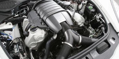
Honda G25A Specifications
| Engine Model: Honda G25A |
| Engine Type: 4-cycle inline 5-cylinder SOHC 20-valve liquid-cooled gasoline |
| Total Displacement: 149.6 cu.in (2.45 L) |
| Rated Engine Power: 187 Hp (140 kW) at 6500 rpm |
| Fuel System Type: Multi-point electronic fuel injection |
____________________________________________________________________________________
The Honda G25A is a 2.5-liter, naturally aspirated
inline-five cylinder engine that served as the higher-displacement counterpart
to the G20A. Produced during the early to mid-1990s, it powered Honda’s premium
JDM sedans and was the sole engine for the Acura Vigor in North America. The
G25A shares the same unique longitudinal, slanted layout as the G20A but
features a larger bore and a significantly longer stroke, emphasizing low-end
torque and refinement.
Its architecture was a direct response to the need for a smooth, compact, and
powerful engine that could fit within Honda’s innovative “FF-midship” platform.
Known for a distinctive exhaust note and a broad torque curve enabled by a
variable induction system, the G25A prioritized a balance of performance and
operational smoothness, bridging the gap between a four-cylinder and a V6.
The Honda G25A engine family encompasses several variants, primarily
differentiated by compression ratio and intake tuning to suit specific markets
and emissions standards. The engine architecture is defined by its longitudinal
mounting orientation, a rarity for a front-wheel-drive application, which
allowed for optimal placement behind the front axle. The cylinder numbering
order is 1-2-3-4-5, with the engine rotating counter-clockwise when viewed from
the pulley end.
The valvetrain utilizes a single overhead camshaft (SOHC) per cylinder bank,
operating four valves per cylinder for a total of 20 valves. The bore measures
85.0 mm (3.35 in) and the stroke is 86.4 mm (3.40 in), resulting in a total
displacement of 2,451 cc (149.6 cu.in). The fuel system is Honda’s PGM-FI
(Programmed Fuel Injection), a multi-point electronic injection system with
sequential fuel delivery.
Power and Torques:
JDM G25A (High Output): Found in higher-spec Honda Inspire and Vigor models. It
features a compression ratio of 10.0:1, producing 190 PS (187 hp / 140 kW) at
6,500 rpm and 237 Nm (175 lb-ft) of torque at 3,800 rpm.
Acura Vigor G25A1: Tuned for the North American market with a lower compression
ratio of 9.0:1. Output is rated at 176 hp (131 kW) at 6,300 rpm and 170 lb-ft
(230 Nm) at 3,900 rpm.
Acura 2.5TL G25A4: A later evolution for the first-generation TL, this variant
utilizes a compression ratio of 9.6:1, maintaining an output of 176 hp but with
a refined engine management calibration for improved drivability and emissions
compliance.
The cylinder block is constructed from high-strength
cast iron, designed to withstand the inherent second-order vibrations of an
inline-five configuration. A deep-skirt design enhances structural rigidity and
reduces noise, vibration, and harshness (NVH). The cylinder bores are machined
directly into the iron casting. The block features an open-deck design at the
top, where the cylinders are unsupported by the upper coolant jacket, aiding in
cooling efficiency around the bore centers.
The engine uses a forged steel crankshaft supported by six main bearings, a
critical feature for managing the increased reciprocating mass of the longer
stroke. The crankshaft incorporates eight balance weights to minimize internal
rotational vibrations. Connecting rods are forged steel, with a fracture-split
design on the big-end caps for precise bearing fitment. The pistons are
lightweight aluminum alloy, featuring a low-friction skirt coating and a
compression height optimized for the SOHC valvetrain.
The cylinder head is a lightweight aluminum alloy
casting utilizing a cross-flow design, with the intake manifold on the rearward
side and the exhaust manifold on the forward side due to the engine’s slanted
orientation. The single overhead camshaft is supported by five cam bearing
journals and is driven by a reinforced rubber timing belt. The valvetrain
employs a SOHC layout with a rocker arm assembly that actuates four valves per
cylinder.
The rocker arms pivot on a stationary shaft and incorporate a roller follower
that contacts the cam lobe, reducing friction. Valve clearance adjustment is
mechanical, utilizing threaded adjusters and locknuts on the rocker arms. The
intake valves measure 33.0 mm (1.30 in) in diameter, while the exhaust valves
measure 28.0 mm (1.10 in). Valve stem seals are of a positive-type design to
control oil consumption. The combustion chamber is a compact pent-roof design
that promotes efficient flame propagation.
The fuel system is a fully electronic PGM-FI system
operating at a nominal pressure of 2.7-3.0 bar (39-43 psi). The system uses a
high-pressure in-tank fuel pump, a fuel filter, and a fuel rail that supplies
four-hole injectors mounted directly above each intake port. The system employs
sequential fuel injection, where the injector timing is synchronized with the
intake valve opening event for each cylinder based on the cylinder
identification sensor. An air intake system incorporates a variable-length
intake manifold with dual plenum chambers.
A tuned intake valve in the manifold switches between long and short intake
runner paths based on engine speed and throttle position, optimizing volumetric
efficiency across the rev range. A hot-wire mass airflow sensor measures
incoming air volume, while a throttle position sensor, coolant temperature
sensor, and oxygen sensors in the exhaust manifold provide closed-loop feedback
to the Engine Control Unit (ECU).
The lubrication system is a fully pressurized, wet-sump
design. A gear-type oil pump, driven directly by the crankshaft nose, draws oil
from a stamped steel oil pan. The pump provides pressurized oil to a full-flow,
spin-on type oil filter mounted externally on the cylinder block. A primary oil
gallery runs the length of the block, feeding the crankshaft main bearings.
Cross-drilled passages in the crankshaft supply oil to the connecting rod
bearings.
A secondary gallery feeds oil upward to the cylinder head through dedicated
passages in the block and head mating surface. The camshaft bearings, rocker arm
shafts, and valve components are lubricated through a controlled orificing
system. The system capacity, including the filter, is 4.3 L (4.5 qt). A piston
cooling oil jet system is not present on the G25A, as the engine’s specific
output and thermal load did not require it.
The cooling system is a thermostatically controlled,
pressurized liquid cooling system. A belt-driven centrifugal water pump
circulates coolant through the block, cylinder head, heater core, and a
single-row tube-and-fin radiator. The thermostat, located in a housing on the
lower intake manifold, maintains operating temperature between 82-88°C
(180-190°F).
The system incorporates a coolant temperature sensor for the ECU and a separate
sender unit for the instrument panel gauge. Coolant flow within the engine is
directed first to the cylinder head and then to the block to manage thermal
expansion and minimize thermal stress on the head gasket. A coolant recovery
reservoir is integrated into the system to maintain proper fill levels and
manage overflow. The total cooling system capacity is approximately 6.5 L (6.9
qt).
The exhaust manifold is a tubular cast iron design with
equal-length runners merging into a single downpipe. The system incorporates a
three-way catalytic converter with an oxygen sensor upstream for closed-loop
fuel control. A secondary oxygen sensor downstream of the catalytic converter is
present on OBD-II compliant variants (such as the G25A4) to monitor converter
efficiency.
| Ignition and Electrical System |
Ignition System: The engine utilizes a fully
transistorized, distributor-based ignition system. The distributor, driven by
the intake camshaft, houses a camshaft position sensor, a cylinder
identification sensor, and a mechanical and vacuum advance mechanism on early
variants, though later models transitioned to electronic advance controlled by
the ECU. Spark plugs are long-reach type with a heat range specified for the
individual engine variant.
Electrical System: The charging system consists
of a 12V, 90-amp alternator. The starting system utilizes a
reduction-gear starter motor mounted on the transmission bellhousing,
engaging a ring gear on the flywheel or flexplate.
Overall length from the timing belt cover to the
transmission mounting face is 710 mm (28.0 in). Width across the valve cover and
intake manifold is 580 mm (22.8 in). Height from the oil pan mounting surface to
the top of the valve cover is 680 mm (26.8 in). The dry weight of the fully
dressed engine, including the intake manifold, exhaust manifold, and all
ancillary components but without fluids, is 165 kg (364 lb).
Valve clearance adjustment is critical due to the
mechanical valvetrain. Inspection and adjustment are required every 40,000 km
(24,000 mi).
Cold valve clearances are:
Intake: 0.23-0.28 mm (0.009-0.011 in)
Exhaust: 0.28-0.33 mm (0.011-0.013 in)
The timing belt replacement interval is 96,000 km (60,000 mi) for rigorous
maintenance schedules, though it is commonly performed earlier due to the
interference nature of the engine. The engine oil should be changed every
5,000-7,500 km (3,000-4,500 mi) depending on driving conditions, using a
viscosity grade of 5W-30 or 10W-30.
The oil filter is replaced concurrently. The coolant should be replaced every
48,000 km (30,000 mi) or 24 months using a silicate-free, phosphate-free
ethylene glycol-based coolant. The spark plug replacement interval is 48,000 km
(30,000 mi) for standard platinum-tipped plugs.
Cylinder Head Bolts, 1st: 30 Nm (22 lb-ft).
Cylinder Head Bolts, 2nd: 60 Nm (44 lb-ft). Then turn all bolts 90°.
Main Bearing Cap Bolts: 54 Nm (40 lb-ft) plus an additional 60° turn.
Connecting Rod Cap Nuts: 34 Nm (25 lb-ft) plus an additional 60° turn.
Camshaft Bearing Cap Bolts: 22 Nm (16 lb-ft).
Rocker Arm Shaft Bolts: 25 Nm (18 lb-ft).
Intake Manifold Nuts: 22 Nm (16 lb-ft).
Exhaust Manifold Nuts: 25 Nm (18 lb-ft).
Valve Adjuster Locknuts: 18 Nm (13 lb-ft).
Spark Plugs: 18 Nm (13 lb-ft).
Oil Pan Bolts: 12 Nm (9 lb-ft).
Flywheel/Flexplate Bolts: 86 Nm (63 lb-ft).
The G25A engine was utilized across a range of premium
Honda and Acura models from 1989 to 1998, primarily in the Japanese and North
American markets.
Honda Inspire / Saber: Second generation (CC2, 1992-1995) and third generation
(UA2, 1995-1998) in 25S and 25V trims.
Honda Vigor: Third generation (CC2, 1992-1995), representing the JDM execution
of the platform.
Honda Ascot / Rafaga: CE5 chassis (1993-1997) in 2.5S and 2.5Xi specifications.
Acura Vigor: North American market (1992-1994), exclusively powered by the G25A1
variant.
Acura 2.5TL: First generation (1995-1998), succeeding the Vigor and utilizing
the G25A4 variant.
____________________________________________________________________________________
| Car Engines Technical Specifications |
| Small Engines Technical Specifications |
| Industrial Engines Technical Specifications |
| Outboard Engines Technical Specifications |