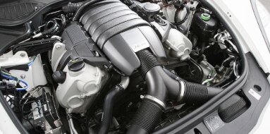
Suzuki G13A Specifications
| Engine Model: Suzuki G13A |
| Engine Type: 4-cycle inline 4-cylinder SOHC 8-valve liquid-cooled gasoline |
| Total Displacement: 80.8 cu.in (1.32 L) |
| Rated Engine Power: 63-70 Hp (47-52 kW) at 6000 rpm |
| Fuel System Type: Carburetor or Electronic Fuel Injection |
____________________________________________________________________________________
The Suzuki G13A is a 1.3-liter inline 4-cylinder petrol
engine that inaugurated the renowned G-family powerplant series in the
mid-1980s. Distinguished by its lightweight aluminum alloy construction, this
engine became a cornerstone for Suzuki’s compact vehicles and early off-roaders,
including the Samurai (SJ413) and the first-generation Swift.
The G13A was engineered with a focus on durability, simplicity, and low vehicle
weight contribution, utilizing a Single Overhead Camshaft (SOHC) configuration
with two valves per cylinder. Its robust bottom end and non-interference valve
timing design provided a margin of safety against timing belt failure,
contributing to its long-standing reputation for reliability in both on-road and
demanding off-road applications across global markets.
Engine Family: Suzuki G-series.
Engine Code: G13A.
Configuration: Inline 4-cylinder, longitudinally or transversely mounted.
Displacement: 1324 cc (80.8 cu.in).
Bore: 74.0 mm (2.91 in).
Stroke: 77.0 mm (3.03 in).
Compression Ratio: 8.9:1.
Firing Order: 1-3-4-2.
Valvetrain Configuration: Single Overhead Camshaft (SOHC), 8 valves.
Valvetrain Drive: Rubber timing belt with automatic tensioner.
Maximum Power Output: 47-52 kW (63-70 hp) at 5500-6000 rpm.
Maximum Torque: 100-103 Nm (74-76 lb-ft) at 3500 rpm.
Engine Redline: 6500 rpm.
Idle Speed (Manual Transmission): 750 rpm ± 50 rpm.
Idle Speed (Automatic Transmission, in gear): 750 rpm ± 50 rpm.
The cylinder block is constructed from cast aluminum
alloy with cast iron cylinder liners pressed into the parent material to provide
a durable wear surface for the piston rings. This aluminum construction
significantly reduces overall engine mass compared to ferrous alternatives. The
block features a closed-deck design at the cylinder head mating surface to
enhance rigidity and gasket sealing.
The crankcase is of a skirtless design, with structural rigidity derived from a
die-cast aluminum oil pan that bolts directly to the lower block face. Five main
bearings support the crankshaft, with the bearing caps manufactured from
sintered iron and located by dowel pins for precise alignment. The block
incorporates cast-in passages for coolant circulation around each cylinder liner
and a full-length oil gallery machined into the right-hand side to supply the
main bearings and valvetrain.
The cylinder head is manufactured from aluminum alloy
using a cross-flow design, with the intake manifold positioned on the rearward
face and the exhaust manifold on the forward face in transverse applications.
The SOHC arrangement operates eight valves via roller rocker arms that pivot on
a fixed shaft. Valve stem diameters are 7.0 mm (0.28 in) for both intake and
exhaust. Intake valves measure 35.0 mm (1.38 in) in diameter, while exhaust
valves measure 31.0 mm (1.22 in).
Valve seat inserts are pressed into the head and machined at 45-degree angles.
Valve clearances are adjustable using threaded adjusters and locknuts on the
rocker arms, requiring periodic maintenance. The combustion chamber is a
hemispherical design with a squish area to promote mixture turbulence. The
cylinder head incorporates a timing belt idler pulley mounting boss and a water
outlet housing integrated into the front face.
The G13A engine was produced with two primary induction
system configurations. Early production versions utilized a dual-throat
downdraft carburetor, commonly a Mikuni or Aisan unit, featuring an automatic
choke mechanism and a mechanical accelerator pump. This carbureted system
operated at fuel pressures of 0.2-0.3 bar (2.9-4.4 psi) delivered by a
low-pressure mechanical fuel pump mounted on the cylinder head.
Later export variants intended for markets with stricter emissions regulations
received a single-point fuel injection (throttle-body injection) system. This
system employed a single centrally positioned injector mounted above the
throttle plate, operating at fuel pressures of approximately 1.0-1.5 bar
(14.5-21.8 psi). The fuel injection configuration included an idle air control
valve, a throttle position sensor, and an oxygen sensor feedback loop for
closed-loop operation.
The lubrication system is a wet-sump type utilizing a
rotor-type oil pump mounted on the front of the crankshaft, driven directly by a
keyed drive sleeve. The pump draws oil from the stamped steel oil pan through a
fixed mesh pickup screen. Oil is directed through a full-flow replaceable
cartridge filter mounted on the cylinder block before being distributed to the
main galleries.
System capacity with filter replacement is 3.5 liters (3.7 qt). The oil pan
incorporates a drain plug with an integrated magnetic element to capture ferrous
wear particles. Recommended oil viscosity is SAE 10W-30 or 10W-40, meeting API
SF, SG, or later classifications. Oil pressure at operating temperature at 3000
rpm is specified at 3.5-4.5 bar (50.8-65.3 psi), while idle pressure is
maintained at a minimum of 0.8 bar (11.6 psi).
The cooling system operates under pressure with a
sealed expansion tank and a radiator cap rated at 0.9 bar (13.1 psi). Coolant
circulation is driven by a centrifugal water pump mounted on the front of the
cylinder block, driven by the same timing belt that operates the camshaft.
System capacity varies by chassis configuration but ranges from 4.5 to 5.5
liters (4.8 to 5.8 qt).
A wax-pellet thermostat is housed in a housing at the water pump inlet,
commencing opening at 82°C (180°F) and reaching full open at 95°C (203°F). A
thermostatically controlled electric cooling fan is employed on transverse
front-wheel-drive applications, while longitudinal off-road applications utilize
a belt-driven engine fan with a viscous coupling. Coolant specified is ethylene
glycol-based, mixed at a 50:50 ratio with distilled water.
| Intake and Exhaust Systems |
Exhaust System: A cast iron exhaust manifold routes to
a single downpipe. Carbureted versions incorporate an exhaust gas recirculation
(EGR) valve mounted on the intake manifold, drawing exhaust gas from a port in
the exhaust manifold.
Intake System: A two-piece intake manifold with a coolant-heated plenum chamber
to assist fuel vaporization during cold starts. The air cleaner housing
incorporates a thermostatic air intake control valve that draws warm air from
the exhaust manifold shield during cold operation.
Distributor-type ignition with vacuum and centrifugal
advance mechanisms. The distributor is mounted on the rear of the cylinder head
in longitudinal applications and on the front in transverse configurations.
Spark plugs are specified with a gap of 0.7-0.8 mm (0.028-0.031 in). Ignition
timing is set at 5-8° before top dead center (BTDC) at idle, with vacuum line
disconnected.
Overall Length: 520 mm (20.47 in).
Overall Width: 590 mm (23.23 in).
Overall Height: 640 mm (25.20 in).
Dry Engine Weight (without coolant, oil, and accessories): 78 kg (172 lb).
Fully Dressed Weight (with intake, exhaust manifolds, alternator, starter, and
distributor): 98 kg (216 lb).
Oil Change Interval: 6000 km (3728 mi) or 6 months
under normal service; 3000 km (1864 mi) under severe duty conditions. Oil Filter
Replacement: Replace at every oil change interval. Timing Belt Replacement:
100,000 km (62,137 mi) for non-interference engine configuration.
Valve Clearance Adjustment: Inspect and adjust every 15,000 km (9321 mi) or 12
months; cold clearance specifications: intake 0.13-0.17 mm (0.005-0.007 in),
exhaust 0.16-0.20 mm (0.006-0.008 in). Spark Plug Replacement: 20,000 km (12,427
mi) for conventional copper-core plugs; 40,000 km (24,855 mi) for
platinum-tipped plugs.
Air Filter Replacement: 20,000 km (12,427 mi) or as indicated by visual
inspection. Fuel Filter Replacement (Carbureted): 30,000 km (18,641 mi) for
inline filter; screen filter in carburetor inlet cleaned as required. Coolant
Replacement: 30,000 km (18,641 mi) or 24 months. Drive Belt (Alternator/Water
Pump): Inspect every 12,000 km (7456 mi); replace if cracking or glazing is
evident.
Cylinder Head Bolts (M10 x 1.25), Stage 1: 20 Nm (15
lb-ft)
Cylinder Head Bolts (M10 x 1.25), Stage 2: 45 Nm (33 lb-ft)
Cylinder Head Bolts (M10 x 1.25), Stage 3: 65 Nm (48 lb-ft)
Main Bearing Cap Bolts (M10 x 1.25): 45 Nm (33 lb-ft)
Connecting Rod Cap Nuts (M8 x 1.0): 30 Nm (22 lb-ft)
Flywheel Bolts (M10 x 1.25): 70 Nm (52 lb-ft)
Camshaft Sprocket Bolt (M12 x 1.25): 60 Nm (44 lb-ft)
Rocker Arm Shaft Bolts (M8 x 1.25): 22 Nm (16 lb-ft)
Intake Manifold Bolts (M8 x 1.25): 20 Nm (15 lb-ft)
Exhaust Manifold Nuts (M8 x 1.25): 25 Nm (18 lb-ft)
Spark Plugs: 20 Nm (15 lb-ft)
Engine Oil Drain Plug: 30 Nm (22 lb-ft)
Timing Belt Tensioner Bolt (M10 x 1.25): 37 Nm (27 lb-ft)
Water Pump Bolts (M8 x 1.25): 20 Nm (15 lb-ft)
Suzuki Samurai / Jimny (SJ413): 1984-1990, longitudinal
front-engine, rear-wheel drive and part-time 4-wheel drive configurations;
carbureted induction.
Suzuki Swift (AA41S / AA43S): 1984-1988, transverse front-engine, front-wheel
drive; carbureted in early production, single-point injection in later export
models.
Suzuki Cultus (AA41S / AA43S): 1984-1988, Japanese domestic market variant of
the Swift with carbureted induction.
Suzuki Forsa (AA41S): 1985-1988, North American market designation for the
Cultus/Swift platform; single-point injection for emissions compliance.
Suzuki Vitara / Escudo (early): Limited application in certain markets during
1988-1989 prior to G16A engine introduction.
Holden Barina (MB / ML): 1985-1989, Australian market rebadged Suzuki Swift with
carbureted G13A engine in MB series and single-point injection in ML series.
____________________________________________________________________________________
| Car Engines Technical Specifications |
| Small Engines Technical Specifications |
| Industrial Engines Technical Specifications |
| Outboard Engines Technical Specifications |