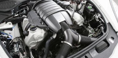
Mitsubishi 4M51 Specifications
| Engine Model: Mitsubishi 4M51 |
| Engine Type: 4-cycle inline 4-cylinder DOHC 16-valve liquid-cooled diesel |
| Total Displacement: 320.3 cu.in (5.25 L) |
| Rated Engine Power: 138-153 Hp (103-114 kW) at 3200 rpm |
| Fuel System Type: Direct injection |
____________________________________________________________________________________
The Mitsubishi 4M51 is a 5.2-liter, naturally
aspirated, inline four-cylinder diesel engine produced primarily during the
1990s for medium-duty commercial vehicle applications. Developed as a
larger-displacement variant within the 4M engine family, which includes the
4M40, the 4M51 was engineered to deliver robust low-end torque and sustained
durability under the demanding operating conditions encountered by delivery
trucks, buses, and other commercial chassis.
The engine’s architecture is defined by its dual overhead camshaft (DOHC)
valvetrain with 16 valves - a configuration that was relatively advanced for a
commercial diesel engine of its era, providing improved volumetric efficiency
compared to the OHV designs common in this segment. The 4M51 found its primary
application within the Mitsubishi Fuso Canter series of light trucks and the
Fuso Rosa bus, where its combination of displacement and mechanical simplicity
made it a preferred choice for operators requiring reliable power in urban and
regional transport roles.
The engine’s production period coincided with the transition from purely
mechanical fuel systems to electronically managed injection, resulting in
variants that differ in emissions compliance and fuel delivery architecture.
The 4M51 engine exemplifies Mitsubishi’s approach to commercial diesel
engineering during the 1990s, prioritizing structural integrity, serviceability,
and consistent torque delivery over peak power output. The engine’s inline-four
configuration with a 118 mm bore and 120 mm stroke yields a displacement of
5,249 cc, placing it in a class suitable for vehicles with gross vehicle weights
in the medium-duty range.
The DOHC valvetrain, with four valves per cylinder, allows for optimized airflow
through the cylinder head, contributing to efficient combustion and improved
fuel economy relative to two-valve designs of comparable displacement. The
camshafts are driven by a gear train rather than a belt or chain, eliminating a
common maintenance concern and ensuring precise timing over extended service
intervals.
The cylinder block and cylinder head are both constructed from cast iron, a
material choice that enhances thermal stability and damping of mechanical
vibrations, though it contributes to the engine’s substantial weight. The direct
injection combustion system, with compression ratios varying between 18.0:1 and
22.5:1 depending on the variant and emissions standard, provides reliable cold
starting and efficient fuel utilization.
Later variants incorporated electronic fuel injection to meet Euro 3 and Euro 4
emissions standards, while earlier versions utilized mechanical injection
systems that are simpler to maintain and repair in field conditions. The
engine’s reputation within commercial fleets is one of longevity, with proper
maintenance allowing for high-mileage service before major overhaul becomes
necessary.
Production Period: 1990s (1993-2000).
Engine Code: 4M51.
Configuration: Inline four-cylinder (I4).
Displacement: 5,249 cc (320.3 cu.in).
Bore: 118.0 mm (4.65 in).
Stroke: 120.0 mm (4.72 in).
Firing Order: 1-3-4-2.
Compression Ratio: 18.0:1 to 22.5:1.
Combustion System: Direct injection.
Aspiration: Naturally aspirated.
Valvetrain: DOHC, 4 valves per cylinder (16 valves total).
Maximum Engine Speed: 3,200-3,500 rpm (governed).
Maximum Power: 103-114 kW (138-153 hp) @ 3,200 rpm.
Maximum Torque: 333-373 Nm (246-275 lb-ft) @ 1,600 rpm.
The 4M51 cylinder block is manufactured from
high-strength cast iron, utilizing a deep-skirt design that extends below the
crankshaft centerline to provide increased rigidity and resistance to distortion
under high cylinder pressures. The block features a closed-deck construction at
the top of the cylinder bores, contributing to improved head gasket sealing and
structural integrity. Five main bearings support the crankshaft, with the
bearing caps secured using high-tensile steel bolts. The cylinder bores are cast
directly into the block and are finished with a precision-honed surface.
The block incorporates the mounting provisions for the fuel injection pump,
driven by the gear train at the front of the engine. Cast-in coolant passages
surround each cylinder bore to provide uniform cooling, while oil galleries are
drilled directly into the block to supply pressurized lubricant to the
crankshaft, camshafts, and other critical components. A balance shaft system is
integrated into the engine block to reduce vibration inherent to the inline-four
configuration, contributing to smoother operation and reduced wear on ancillary
components.
The cylinder head is constructed from cast iron,
selected for its thermal stability and compatibility with the cast-iron block to
ensure uniform expansion rates and reliable head gasket sealing. The dual
overhead camshaft (DOHC) arrangement utilizes four valves per cylinder - two
intake and two exhaust - with the valves arranged in a pent-roof combustion
chamber design to optimize flow characteristics. The camshafts are driven by a
gear train from the crankshaft, eliminating the need for timing belts or chains
and their associated maintenance intervals.
The valve actuation system employs roller rocker arms with an adjustment
mechanism for setting valve clearances. The valve clearances are specified with
the engine cold; intake valve clearance is 0.20 mm (0.008 in), and exhaust valve
clearance is 0.30 mm (0.012 in) for mechanically adjusted variants. Later
electronically managed variants utilize a different specification with hydraulic
lash adjusters. The cylinder head incorporates the intake and exhaust ports on
opposite sides, with the intake ports designed to create swirl motion within the
cylinder to enhance air-fuel mixing.
The fuel system configuration varies according to the
production year and emissions compliance level. Earlier variants utilize a
mechanical inline injection pump driven directly by the engine’s gear train,
delivering fuel through individual high-pressure lines to the injectors.
Injection timing is adjustable and is set according to the specifications on the
engine data plate, generally within the range of 13° to 15° before top dead
center. Later variants intended to meet Euro 3 or Euro 4 emissions standards
employ an electronically controlled common rail injection system, with injection
pressures and timing managed by an engine control unit.
The mechanical lift pump, mounted on the cylinder block, draws fuel from the
tank and delivers it through a fuel filter with an integrated water separator.
Excess fuel not injected during the combustion cycle is returned to the fuel
tank. The injectors are of the nozzle-and-holder type, designed to atomize fuel
into a fine spray pattern suitable for direct injection into the combustion bowl
machined into the piston crown.
The lubrication system employs a wet-sump design with a
gear-type oil pump mounted within the front timing gear case, driven directly by
the crankshaft. The pump draws oil from the sump through a screened pickup tube
and delivers it through a full-flow spin-on oil filter mounted externally on the
cylinder block. The filtered oil is distributed through internal galleries to
the crankshaft main bearings, connecting rod bearings, camshaft bearings, and
the rocker arm assembly.
A pressure relief valve is integrated into the oil pump assembly to maintain
consistent oil pressure and prevent over-pressurization at higher engine speeds.
An oil cooler, either water-to-oil or air-to-oil depending on the vehicle
application, is incorporated to manage oil temperature during sustained
high-load operation. Total system capacity, including the filter and cooler, is
approximately 9.0 to 10.0 liters (9.5 to 10.6 qt) depending on the vehicle
platform and sump configuration.
The cooling system is a pressurized water-cooled design
utilizing a crossflow radiator with a fin-and-tube core construction. A
centrifugal water pump, driven by the engine’s accessory drive belt, circulates
coolant through the cylinder block, cylinder head, and radiator. A wax-element
thermostat is positioned in the coolant outlet housing to regulate coolant flow
and maintain the engine within its optimal operating temperature range. The
system incorporates an expansion tank to accommodate coolant expansion during
operation and to facilitate the removal of air from the system.
A viscous fan or an electric fan, depending on the vehicle platform, provides
airflow across the radiator. The cooling system is designed to manage the
significant thermal load generated by the 5.2-liter displacement, particularly
during sustained high-power operation such as hill climbing or fully loaded
urban delivery cycles. Coolant capacity varies by vehicle application but
generally ranges from 12.0 to 14.0 liters (12.7 to 14.8 qt).
| Intake and Exhaust Systems |
Intake System: The intake system consists of an air
cleaner housing with a replaceable dry-type filter element, ducting to the
intake manifold, and the intake manifold itself, which is constructed from cast
iron and is designed with runners sized to optimize airflow velocity across the
engine’s operating range. The DOHC valvetrain allows for a straight-port intake
design that improves flow efficiency.
Exhaust System: The exhaust system utilizes a cast iron exhaust manifold
designed to withstand thermal cycling without warping. The exhaust gases are
directed through a single exhaust pipe to a silencer. Later production models
incorporate an exhaust gas recirculation (EGR) system to reduce NOx emissions,
with the EGR cooler mounted to the cylinder head.
| Electrical and Starting System |
Electrical System: The engine is equipped with a
12-volt or 24-volt electrical system depending on the vehicle application. The
starter motor is a reduction-gear type, sized to provide adequate cranking
torque for the high compression ratio. The charging system consists of an
alternator with an internal voltage regulator. Electronically managed variants
incorporate sensors including a crankshaft position sensor, coolant temperature
sensor, and intake air pressure sensor.
Starting System: Glow plugs are installed in the cylinder head to assist with
cold starting. The glow plug system is controlled by a timer or electronic
control unit that activates the glow plugs for a predetermined duration based on
coolant temperature.
Overall Length: 920 mm (36.2 in)
Overall Width: 680 mm (26.8 in)
Overall Height: 850 mm (33.5 in)
Dry Weight (complete engine): 380-420 kg (838-926 lbs)
Engine Oil: SAE 15W-40 or 10W-30 meeting API CI-4 or
higher classification for diesel engines. Oil Capacity (with filter change):
9.0-10.0 L (9.5-10.6 qt). Oil Change Interval: 5,000-8,000 km (3,100-5,000 mi)
under normal conditions; shorter intervals under severe service.
Fuel Filter: Replace at 15,000-20,000 km (9,300-12,400 mi) intervals; water
separator drain as required. Coolant Capacity: 12.0-14.0 L (12.7-14.8 qt)
depending on vehicle platform. Coolant Specification: Ethylene glycol-based
antifreeze with corrosion inhibitors; replace every 2 years or 40,000 km (24,800
mi).
Valve Clearance (Cold): Intake: 0.20 mm (0.008 in); Exhaust: 0.30 mm (0.012 in)
for mechanical adjustment variants. Engine Idle Speed: 650-750 rpm. Compression
Pressure: Standard: 2.75-3.00 MPa (399-435 psi); Minimum service limit: 2.00 MPa
(290 psi).
Connecting Rod Cap Bolts: 68.6 Nm (7.0 kgm, 50.6 lb-ft)
+ 90°
Main Bearing Cap Bolts: 59.0 Nm (6.0 kgm, 43.5 lb-ft) + 90°
Cylinder Head Bolts, Stage 1: 75 Nm (7.6 kgm, 55 lb-ft)
Cylinder Head Bolts, Stage 2: 150 Nm (15.3 kgm, 111 lb-ft) + 90°
Flywheel/Flexplate to Crankshaft: 110-120 Nm (11.2-12.2 kgm, 81-89 lb-ft)
Intake Manifold to Cylinder Head: 25-30 Nm (2.5-3.1 kgm, 18-22 lb-ft)
Exhaust Manifold to Cylinder Head: 30-35 Nm (3.1-3.6 kgm, 22-26 lb-ft)
Injection Pump Mounting Nuts: 20-25 Nm (2.0-2.5 kgm, 15-18 lb-ft)
Injector Holders: 60-70 Nm (6.1-7.1 kgm, 44-52 lb-ft)
Camshaft Bearing Caps: 20-25 Nm (2.0-2.5 kgm, 15-18 lb-ft)
Mitsubishi Fuso Canter
(6th Generation)
FE Series: FE512, FE514, FE525, FE527, FE529, FE542E, FE545, FE547, FE549,
FE639, FE649, FE659 with 4M51 engine.
FB Series: FB631, FB641, FB649 (cab-over configurations).
Mitsubishi Fuso Rosa
Bus Applications: Rosa BE632, BE637, BE639, BE649 models utilizing the 4M51
engine for passenger transport.
Other Applications
Industrial Equipment: The 4M51 engine and its derivatives have been utilized in
construction machinery, agricultural equipment, and generator sets where its
robust construction and mechanical simplicity are valued.
Export Markets: The engine was supplied to various markets in Asia, Africa, the
Middle East, and South America through Mitsubishi’s commercial vehicle
distribution channels.
____________________________________________________________________________________
| Car Engines Technical Specifications |
| Small Engines Technical Specifications |
| Industrial Engines Technical Specifications |
| Outboard Engines Technical Specifications |