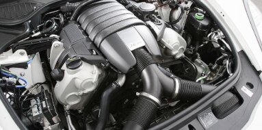
Volvo B21ET Specifications
| Engine Model: Volvo B21ET |
| Engine Type: 4-cycle 4-cylinder SOHC 8-valve turbocharged liquid-cooled gasoline |
| Total Displacement: 129.8 cu.in (2.12 L) |
| Rated Engine Power: 155 Hp (114 kW) at 5500 rpm |
| Fuel System Type: Continuous injection system (CIS) |
____________________________________________________________________________________
The Volvo B21ET represents a landmark in Volvo’s
engineering history, serving as the company’s first mass-produced turbocharged
passenger car engine. Introduced in the early 1980s, this 2.1-liter inline-four
belongs to the venerable Redblock family, a series of overhead camshaft
powerplants renowned for exceptional durability and robust construction. The
B21ET was developed to deliver substantial performance gains over naturally
aspirated counterparts while maintaining the longevity for which Volvo had
become known.
Powering the iconic 240 Turbo models - the “Flying Brick” sedans, coupes, and
estates - this engine combined a low-compression bottom end with a Garrett T3
turbocharger and Bosch mechanical fuel injection. Its foundation of forged
internal components and a non-interference valvetrain design has made it a
favored platform for performance enthusiasts seeking reliable power upgrades
decades after its original production ceased.
The engine operates as a four-stroke, spark-ignited, turbocharged unit. Its
architecture is defined by a cast-iron block and an aluminum cross-flow cylinder
head, arranged in a longitudinal configuration for rear-wheel-drive
applications.
Engine Type: Inline 4-cylinder, 8 valves.
Valvetrain: Belt-driven SOHC with mechanical valve lifters.
Displacement: 2127 cc (129.8 cu.in).
Bore: 92.0 mm (3.62 in).
Stroke: 80.0 mm (3.15 in).
Compression Ratio: 7.5:1.
Firing Order: 1-3-4-2.
Fuel System: Bosch K-Jetronic continuous mechanical fuel injection.
Turbocharger: Garrett T3.
Maximum Power: 155 hp (114 kW) at 5500 rpm.
Maximum Torque: 240 Nm (177 lb-ft) at 3750 rpm.
Boost Pressure (Stock): 0.65 bar (9.4 psi).
Maximum Engine Speed: 6000 rpm (governed by fuel cut).
Idle Speed: 900 ± 50 rpm.
The cylinder block is manufactured from high-nickel
cast iron, providing exceptional rigidity, wear resistance, and thermal
stability under elevated boost pressures. This material selection contributes to
the engine’s reputation for sustaining high mileage and accommodating
significant power increases. The block features a deep-skirt design, extending
the cylinder walls below the crankshaft centerline for enhanced structural
support.
Five main bearings support the crankshaft, with the bearing caps secured by
through-bolts. The block incorporates cast-in coolant passages surrounding each
cylinder bore to ensure uniform temperature distribution. An oil return passage
is cast into the block specifically for the turbocharger drainage system.
The cylinder head is constructed from cast aluminum
alloy and follows a cross-flow design, with the intake manifold on the left side
and the exhaust manifold on the right side for longitudinal vehicle layouts. The
single overhead camshaft operates eight valves via mechanical lifters, requiring
periodic valve clearance adjustments. For turbocharged applications, Volvo
specified the “160” or “398” casting cylinder heads, which featured enhanced
material density and were fitted with sodium-filled exhaust valves to improve
heat dissipation under sustained high-temperature operation.
Valve Arrangement: 8 valves; SOHC with mechanical lifters.
Intake Valve Diameter: 44.0 mm (1.73 in).
Exhaust Valve Diameter: 38.0 mm (1.50 in) for sodium-filled units.
Valve Stem Diameter: 8.0 mm (0.31 in).
Valve Seat Angle: Intake 45°, Exhaust 45°.
Valve Clearance (Cold): Intake 0.35-0.45 mm (0.014-0.018 in).
Valve Clearance (Cold): Exhaust 0.40-0.50 mm (0.016-0.020 in).
The camshaft is driven by a toothed rubber timing belt. A critical feature of
the B21ET is its non-interference design; should the timing belt fail, the
piston crowns do not make contact with the valves, preventing catastrophic
internal damage.
The fuel system employs the Bosch K-Jetronic continuous
injection system (CIS), a mechanically controlled setup that relies on fuel
pressure and airflow to meter delivery. A fuel distributor assembly directs fuel
continuously to eight injector lines, with fuel flow regulated by a movable air
sensor plate located within the intake air stream. This system operates at high
pressure and does not require electronic engine management for basic fuel
delivery, though a Lambda-sond oxygen sensor and electronic control unit were
incorporated on later versions to enable closed-loop mixture control and
catalytic converter compatibility.
System Type: Bosch K-Jetronic (CIS) continuous mechanical injection.
System Pressure: 5.2-5.5 bar (75-80 psi).
Control Pressure (Warm): 3.4-3.8 bar (49-55 psi).
Cold Start Valve: Thermo-time controlled enrichment for starting.
Fuel Pump: In-tank lift pump paired with external high-pressure roller-cell
pump. A warm-up regulator modifies control pressure based on engine temperature,
enriching the mixture during cold starts and leaning it as operating temperature
is reached.
The lubrication system is a full-pressure, wet-sump
design engineered to accommodate the additional demands of turbocharger
operation. A gear-type oil pump, driven by the crankshaft, draws lubricant from
a cast aluminum oil pan and circulates it through a full-flow oil filter. An
integrated oil cooler, mounted at the oil filter housing, uses engine coolant to
stabilize oil temperature under high-load conditions.
Engine Oil Capacity with Filter: 4.8 L (5.1 qt).
Engine Oil Capacity without Filter: 4.2 L (4.4 qt).
Recommended Oil Grade: SAE 10W-30 or 15W-40 meeting API SF, SG, or later
classifications; synthetic or semi-synthetic formulations preferred for
turbocharger protection. Oil Pressure at Operating Speed: 3.5-5.0 bar (51-73
psi) at 2000 rpm.
Turbocharger Oil Supply: Pressurized feed from the main oil gallery with a
restricted orifice to control flow. The oil pump relief valve maintains
consistent pressure across the engine speed range. The turbocharger drains via a
gravity-fed return line to the oil pan, requiring unobstructed flow to prevent
bearing coking.
The cooling system is a pressurized, sealed circuit
utilizing a cross-flow radiator and a belt-driven centrifugal water pump. A
wax-type thermostat regulates coolant flow to maintain optimal operating
temperatures. The system incorporates a coolant-fed oil cooler integrated with
the oil filter housing, which simultaneously cools the engine oil and aids in
warming it during cold starts.
Coolant Capacity (Total System): 8.5 L (9.0 qt).
Thermostat Opening Temperature: 87°C (189°F).
Radiator Cap Pressure Rating: 0.75 bar (11 psi).
Recommended Coolant: Ethylene glycol-based antifreeze with corrosion inhibitors,
mixed 50:50 with distilled water. Coolant flow is directed through the cylinder
block, cylinder head, and turbocharger center housing. The turbocharger
incorporates both coolant feed and return lines for water-cooled bearing housing
units on later production engines, reducing heat soak after shutdown.
The engine utilizes a distributor-based electronic
ignition system. Early versions employed a breakerless hall-effect distributor
integrated with the Bosch ignition control unit. The distributor is driven by
the camshaft via a gear on the auxiliary shaft, which also drives the fuel
distributor and oil pump.
Ignition Timing (Static): 12° before top dead
center (BTDC) at idle with vacuum advance disconnected. Ignition Timing
(Full Load): 24-28° BTDC at 3000 rpm. Spark Plug Type: Bosch WR7DC or
equivalent. Spark Plug Gap: 0.70-0.80 mm (0.028-0.031 in).
The Garrett T3 turbocharger features a turbine housing
optimized for rapid spooling. Early units utilized a pressure-actuated wastegate
to regulate boost pressure. A bypass valve (recirculation valve) is integrated
to prevent compressor surge during throttle closure. Intake air passes through a
dry-element air filter and a plastic air box before entering the turbocharger
compressor inlet.
Timing Drive: The camshaft is driven by a reinforced
rubber timing belt with internal teeth. A spring-loaded tensioner maintains
correct belt tension. The belt requires periodic replacement as a preventive
maintenance measure. Due to the non-interference valvetrain design, belt failure
does not result in valve-to-piston contact.
Exhaust System: A cast iron exhaust manifold with short, equal-length runners
directs exhaust gases to the turbocharger turbine housing. A single exhaust pipe
routes from the turbocharger outlet through a catalytic converter on Lambda-sond
equipped models and a rear muffler.
Overall Length (Accessory Drive to Flywheel): 720 mm
(28.3 in).
Overall Width (Intake Manifold to Exhaust Manifold): 610 mm (24.0 in).
Overall Height: 710 mm (28.0 in).
Weight (Dry, Complete with Manifolds, Turbocharger, and Flywheel): 175 kg (386
lb).
Oil Change Interval: 5000 km (3100 mi) or 6 months for
conventional oil; 10,000 km (6200 mi) for synthetic oil under normal operation.
Timing Belt Replacement Interval: 50,000 km (31,000 mi) for early production;
revised to 80,000 km (50,000 mi) for later belt formulations. Coolant
Replacement Interval: 2 years or 40,000 km (25,000 mi).
Spark Plug Replacement Interval: 20,000 km (12,500 mi) for copper-core plugs;
longer intervals for platinum-tipped equivalents. Air Filter Replacement: 20,000
km (12,500 mi) under normal conditions; more frequent replacement in dusty
environments. Valve Clearance Inspection: 20,000 km (12,500 mi); adjustment
using replaceable shims or screw-and-locknut adjusters depending on production
variant.
Fuel Filter Replacement: 40,000 km (25,000 mi). Turbocharger Care: Engine idle
cool-down period of 30-60 seconds before shutdown recommended after sustained
high-load operation to prevent oil coking in the turbocharger bearing housing.
Cylinder Head Bolts (Stage 1): 20 Nm (15 lb-ft).
Cylinder Head Bolts (Stage 2): 60 Nm (44 lb-ft).
Main Bearing Cap Bolts: 80 Nm (59 lb-ft).
Connecting Rod Cap Nuts: 60 Nm (44 lb-ft).
Camshaft Bearing Cap Bolts: 12 Nm (9 lb-ft).
Camshaft Timing Belt Sprocket Bolt: 80 Nm (59 lb-ft).
Flywheel/Flexplate Bolts: 60 Nm (44 lb-ft).
Intake Manifold Bolts: 20 Nm (15 lb-ft).
Exhaust Manifold Nuts: 35 Nm (26 lb-ft).
Turbocharger to Exhaust Manifold Nuts: 40 Nm (30 lb-ft).
Water Pump Bolts: 10 Nm (7 lb-ft).
Oil Filter: 15 Nm (11 lb-ft).
Spark Plugs: 25 Nm (18 lb-ft).
Fuel Distributor Mounting Bolts: 10 Nm (7 lb-ft).
The Volvo B21ET was produced primarily from 1981
through 1984, serving as the flagship performance engine across the 200 series
range in European, Australian, and select other markets.
Volvo 244 Turbo: The four-door sedan variant, representing the most common
application. It featured distinctive “Turbo” badging, a front air dam, and
upgraded suspension components.
Volvo 242 Turbo: The two-door coupe version, prized for its sportier appearance
and reduced weight. This model became an icon of 1980s performance touring.
Volvo 245 Turbo: The five-door estate (wagon), offering the turbocharged
powertrain in a highly utilitarian body style, combining performance with
exceptional cargo capacity.
Volvo 260 Series (Limited Markets): A small number of early turbo conversions
using the B21ET were offered in select regions prior to full series production.
Later variants, including the B21FT (intercooled) and the B230ET/FT, succeeded
the B21ET, though the original B21ET remains notable for its forged internal
components and foundational role in establishing Volvo’s performance heritage.
____________________________________________________________________________________
| Car Engines Technical Specifications |
| Small Engines Technical Specifications |
| Industrial Engines Technical Specifications |
| Outboard Engines Technical Specifications |