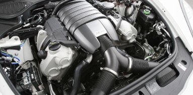
Volvo B20A Specifications
| Engine Model: Volvo B20A |
| Engine Type: 4-cycle inline 4-cylinder OHV 8-valve liquid-cooled gasoline |
| Total Displacement: 121.2 cu.in (1.98 L) |
| Rated Engine Power: 90-100 Hp (67-75 kW) at 4800 rpm |
| Fuel System Type: Carburetor |
____________________________________________________________________________________
The Volvo B20A is a 2.0-liter, naturally aspirated
inline-four gasoline engine that stands as one of the most celebrated
powerplants in Volvo’s automotive history. Introduced in 1969 as a displacement
increase over the legendary B18, the B20A became the foundation of Volvo’s
overhead valve (OHV) family, earning a reputation for exceptional durability,
robust construction, and a character defined by strong low-end torque. This
engine powered Volvo through a transformative era, from the final years of the
140 series into the early production of the 240 series, solidifying the brand’s
image of producing vehicles capable of enduring extreme mileage.
The B20A’s architecture is a study in functional simplicity. It retains the
cast-iron block and cylinder head construction of its predecessor, prioritizing
longevity and thermal stability over weight savings. The valvetrain utilizes a
gear-driven camshaft located in the cylinder block, operating the valves via
pushrods and rocker arms. This configuration, while a departure from the
overhead cam designs that would follow, provided a compact, reliable, and easily
serviceable engine.
The B20A was specifically calibrated for economy and durability, featuring a
single carburetor and a compression ratio suited for lower-octane fuels,
distinguishing it from its higher-performance siblings, the B20B and B20E. Its
reputation for being nearly indestructible, combined with a non-interference
valve design, has made it a perennial favorite for vintage Volvo restorations
and daily driving alike.
The B20A is a water-cooled, four-stroke, spark-ignition inline-four. Its design
emphasizes mechanical simplicity and robust construction, characteristics that
contributed to its long service life.
Engine Type: Inline-4, OHV (Overhead Valve), naturally aspirated.
Displacement: 1,986 cc (121.2 cu.in).
Bore: 88.9 mm (3.50 in).
Stroke: 80.0 mm (3.15 in).
Compression Ratio: 8.7:1.
Valvetrain: OHV (pushrod), 8-valve (2 valves per cylinder).
Firing Order: 1-3-4-2.
Ignition System: Contact breaker (points) distributor, later models with
electronic ignition.
Idle Speed: 750-850 rpm.
The B20A was conservatively tuned to prioritize low-end torque and fuel economy.
Power figures are quoted in both DIN (Deutsches Institut fur Normung) and SAE
(Society of Automotive Engineers) standards depending on the market and era.
Maximum Power (DIN): 82-90 hp @ 4,700-4,800 rpm (61-67 kW).
Maximum Power (SAE): 90-100 hp @ 4,700-4,800 rpm (67-75 kW).
Maximum Torque: 157-162 Nm @ 2,300-2,500 rpm (116-119 lb-ft).
Maximum Engine Speed: 6,000 rpm.
The cylinder block is constructed from high-strength
cast iron, a material chosen for its exceptional rigidity, thermal stability,
and resistance to wear. This robust construction contributes directly to the
engine’s reputation for longevity and its ability to withstand high-mileage
operation without significant bore distortion. The block is a deep-skirt design,
extending below the crankshaft centerline, providing substantial support for the
main bearing caps and minimizing flex under load.
Within the block, the cylinders are formed directly into the iron casting,
eliminating the need for separate cylinder liners. This design allows for
multiple overbore options during rebuilding, a feature highly valued in the
engine’s aftermarket support. The cylinder bores are precision-honed with a
cross-hatch pattern to promote oil retention and piston ring seating. The
camshaft is mounted within the cylinder block on three bearings, positioned
adjacent to the crankshaft and driven directly by a gear train.
The crankshaft is supported by five main bearings, providing robust support for
the rotating assembly and contributing to the engine’s inherent smoothness. The
gear-driven timing system, oil pump, and distributor are all housed within the
front timing cover, creating a compact front-end assembly.
The cylinder head is manufactured from cast iron,
matching the block material to ensure uniform thermal expansion and a consistent
head gasket seal across the engine’s operating temperature range. The head
features a cross-flow design with intake and exhaust ports on opposite sides,
optimizing airflow through the combustion chambers. The valve arrangement
consists of two valves per cylinder - one intake and one exhaust - operated by
pushrods and rocker arms from the camshaft located in the block.
The valvetrain is a robust system: the camshaft rotates within the block, acting
upon mechanical lifters (tappets) that translate motion upward through hollow
pushrods to the rocker arms. The rocker arms, mounted on a shaft running the
length of the cylinder head, pivot to open the valves against the pressure of
coil springs. Valve clearance is adjusted manually via setscrews and locknuts on
the rocker arms, a straightforward maintenance procedure.
Early cylinder heads were designed for operation with leaded fuel, which
provided lubrication for the valve seats. For sustained operation on modern
unleaded fuel, installation of hardened valve seats is a common and recommended
modification to prevent valve recession.
Valves: 8 total (2 per cylinder)
Valve Lifters: Mechanical (solid) tappets with manual adjustment
Camshaft Drive: Gear-driven (fiber composite or steel gears)
Combustion Chamber: Wedge design with angled valves
Valve Seat Inserts: Replaceable inserts
The B20A utilizes a single constant-depression
carburetor, primarily the Zenith-Stromberg 175 CD2. This carburetor design
employs a vacuum-operated piston to vary the venturi area, providing a
consistent air-fuel mixture across a wide range of engine speeds and loads. The
carburetor is equipped with an automatic choke mechanism, which uses a
bi-metallic spring and coolant passage to regulate cold-start enrichment.
The fuel delivery system consists of a mechanical fuel pump mounted to the side
of the cylinder block, actuated by an eccentric lobe on the camshaft. The pump
draws fuel from the fuel tank through a replaceable in-line filter and delivers
it to the carburetor float bowl. The carburetor incorporates an integral float
chamber with a needle and seat valve to maintain a constant fuel level. A manual
throttle linkage connects the accelerator pedal directly to the carburetor
throttle plate, providing a direct mechanical connection and predictable
throttle response.
Carburetor Type: Zenith-Stromberg 175 CD2 (single)
Fuel Pump: Mechanical diaphragm pump
Fuel Requirement: Regular unleaded gasoline (91 RON)
Fuel Filter: In-line replaceable filter
The lubrication system is a full-flow, pressure-fed
design utilizing a gear-type oil pump. The oil pump is mounted to the front of
the engine and driven by the same gear train that drives the camshaft and
distributor. This gear-driven pump is known for its reliability and consistent
oil pressure delivery across the engine speed range.
Oil is drawn from a stamped steel oil pan through a screened pickup tube and
circulated through a spin-on, full-flow oil filter mounted externally on the
engine block. The system incorporates a pressure relief valve to maintain oil
pressure within specified limits and prevent over-pressurization at high engine
speeds. The lubrication circuit supplies pressurized oil to the crankshaft main
bearings, connecting rod bearings, camshaft bearings, and mechanical tappets.
The rocker arm shaft is lubricated through passages in the cylinder head, with
oil delivered via hollow pushrods that feed oil to the rocker arm pivots.
Recommended Oil Viscosity: 10W-30, 15W-40, or 20W-50
Oil Specification: API SF, SG, or higher
Oil Capacity (with filter): 3.75 L (4.0 US qt)
Oil Pressure (at operating temperature, 2,000 rpm): 3.0-4.0 bar (44-58 psi)
The cooling system is a pressurized, thermosiphon-type
system designed to manage the thermal load of the cast-iron engine. It features
a belt-driven centrifugal water pump, a cross-flow brass or aluminum radiator
with a mechanical engine-driven cooling fan, and a wax-type thermostat. The
thermostat begins to open at approximately 82°C (180°F) and is fully open by
95°C (203°F).
The water pump is mounted to the front of the cylinder block and is driven by
the same belt that drives the alternator. The coolant circulates from the
radiator into the block, passing around the cylinders before flowing upward into
the cylinder head.
The cast-iron construction of both block and
head provides a large thermal mass, which contributes to stable
operating temperatures but also requires a longer warm-up period. A
separate coolant circuit supplies the heater core for cabin climate
control and, in some applications, the automatic choke mechanism on the
carburetor.
Coolant Capacity (total system): 7.5 L (7.9 US qt)
Recommended Coolant: Ethylene-glycol based, phosphate-free long-life
coolant
Thermostat Opening Temperature: 82°C (180°F)
| Intake and Exhaust Systems |
Intake System: The intake manifold is a cast-iron unit
designed to accept the single Zenith-Stromberg carburetor. The manifold features
internal passages heated by engine coolant to assist in fuel vaporization during
cold operation, improving drivability and reducing carburetor icing in cold
climates.
Exhaust System: The exhaust manifold is a cast-iron log-style design, collecting
exhaust gases from all four cylinders into a single outlet. The system is
designed for durability, with a simple, robust construction that resists
cracking under thermal cycling. A single exhaust pipe routes to a muffler and
tailpipe system.
The B20A originally employed a contact breaker (points)
distributor system. The distributor is driven by a gear from the camshaft and
houses the centrifugal and vacuum advance mechanisms. The ignition coil is
mounted on the engine bulkhead or inner fender.
Later models in certain markets received an
electronic ignition system, replacing the contact breaker with a
magnetic pickup module for reduced maintenance and more consistent
timing. Spark Plugs: Champion N9Y or NGK BPR6ES equivalent. Spark Plug
Gap: 0.7-0.8 mm (0.028-0.031 in). Ignition Timing: 10°-12° BTDC at idle
with vacuum advance disconnected.
Overall Length: 680 mm (26.8 in)
Overall Width: 590 mm (23.2 in)
Overall Height: 710 mm (28.0 in)
Dry Weight (complete engine): 150 kg (331 lb)
Valve Clearance (cold engine): Intake: 0.45-0.55 mm
(0.018-0.022 in); Exhaust: 0.45-0.55 mm (0.018-0.022 in). Valve Clearance
Adjustment Interval: 8,000 km (5,000 miles) or as required based on noise.
Camshaft Timing Gear: Fiber gear replacement recommended at 80,000-100,000 km
(50,000-62,000 miles) or conversion to steel gear for permanent reliability.
Engine Oil Change Interval: 5,000-8,000 km (3,000-5,000 miles) depending on
driving conditions. Spark Plug Replacement Interval: 16,000 km (10,000 miles)
for conventional plugs. Coolant Replacement Interval: 40,000 km (25,000 miles)
or 2 years.
Drive Belt (Accessory): Inspect for cracks and tension at regular intervals;
replacement as needed. Fuel Filter Replacement: 16,000 km (10,000 miles).
Ignition Points Replacement: 8,000 km (5,000 miles) for contact breaker systems.
Non-Interference Design: Timing gear failure does not result in piston-to-valve
contact.
Cylinder Head Bolts, Stage 1: 60 Nm (44 lb-ft)
Cylinder Head Bolts, Stage 1: 85-95 Nm (63-70 lb-ft)
Main Bearing Cap Bolts: 80 Nm (59 lb-ft)
Connecting Rod Cap Nuts: 55 Nm (41 lb-ft)
Crankshaft Pulley Bolt: 150 Nm (111 lb-ft)
Flywheel/Flexplate Bolts: 70 Nm (52 lb-ft)
Camshaft Gear Bolt: 55 Nm (41 lb-ft)
Rocker Arm Shaft Bolts: 20 Nm (15 lb-ft)
Intake Manifold Bolts: 30 Nm (22 lb-ft)
Exhaust Manifold Nuts: 30 Nm (22 lb-ft)
Spark Plugs: 25 Nm (18 lb-ft)
Oil Pan Bolts: 10 Nm (7 lb-ft)
Oil Pump Mounting Bolts: 10 Nm (7 lb-ft)
Water Pump Bolts: 20 Nm (15 lb-ft)
Carburetor Mounting Nuts: 20 Nm (15 lb-ft)
The Volvo B20A served as the standard entry-level
powerplant across Volvo’s model lineup during the late 1960s and early 1970s,
valued for its durability, fuel economy, and low-end torque.
Volvo 140 Series (142, 144, 145, 1970-1974): The B20A was the primary engine for
base and “L” (economy) models of the 140 series. It replaced the B18A in 1969
and remained in production through the end of the 140 series. This application
included sedans (142, 144) and station wagons (145), where the engine’s torque
characteristics were well-suited for load-carrying duties.
Volvo 240 Series (242, 244, 1975-1976): Early production of the 240 series
utilized the B20A in entry-level models before the transition to the overhead
cam B19 and B21 engines. These vehicles represent the final automotive
application of the B20 family in passenger cars.
Volvo P1800 (select export markets): While the majority of P1800 sports coupes
received the higher-output dual-carburetor B20B or fuel-injected B20E, certain
base export versions, particularly in markets with fuel economy or emissions
requirements, were fitted with the single-carburetor B20A.
Volvo Penta Marine and Industrial Applications: The B20A was widely adapted for
marine and industrial use under the Volvo Penta brand, designated as the AQ115
(marine) or BB115 (industrial). In these applications, the engine was often
fitted with specialized cooling systems (raw water or heat exchanger) and
heavy-duty components for continuous-duty operation.
____________________________________________________________________________________
| Car Engines Technical Specifications |
| Small Engines Technical Specifications |
| Industrial Engines Technical Specifications |
| Outboard Engines Technical Specifications |