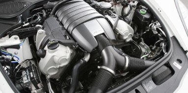
Toyota 3FE Specifications
| Engine Model: Toyota 3FE |
| Engine Type: 4-cycle inline 6-cylinder OHV 12-valve liquid-cooled gasoline |
| Total Displacement: 241.2 cu.in (3.95 L) |
| Rated Engine Power: 155 Hp (116 kW) at 4000 rpm |
| Fuel System Type: Electronic fuel injection |
____________________________________________________________________________________
The Toyota 3F-E is a 4.0-liter, naturally aspirated
inline-six gasoline engine produced from 1988 to 1992, representing the
electronic fuel-injected evolution of the carbureted 3F engine. Developed
specifically for the heavy-duty demands of the Toyota Land Cruiser, this power
unit was engineered to prioritize extreme durability, low-end torque, and
operational simplicity over outright power or fuel efficiency.
The 3F-E retains the foundational architecture of the F-series engine family - a
cast iron block and cylinder head with an overhead valve (OHV) pushrod
valvetrain - while introducing electronic fuel injection to improve cold-start
performance, throttle response, and emissions compliance.
The engine’s gear-driven camshaft, seven-main-bearing crankshaft, and low 8.1:1
compression ratio contribute to its reputation for exceptional longevity and
tolerance of lower-grade fuels in remote operating environments. While its power
output of 155 hp and torque peak at 2,200 rpm align with the Land Cruiser’s
off-road and towing requirements rather than highway performance, the 3F-E
remains a benchmark for robust, serviceable engine design in the overland and
vintage 4x4 communities.
The Toyota 3FE is a four-stroke, water-cooled, inline-six gasoline engine with a
total displacement of 3,955 cc (241.2 cu.in). The bore and stroke dimensions are
94.0 mm and 95.0 mm, respectively, creating a nearly square configuration that
balances low-end torque with moderate-rpm power delivery. The valvetrain employs
an overhead valve (OHV) design with two valves per cylinder - one intake and one
exhaust - for a total of 12 valves. The camshaft is positioned within the
cylinder block and actuates the valves through pushrods and rocker arms.
The fuel system utilizes electronic fuel injection (EFI) with multi-point
injection, replacing the carburetor found on the earlier 3F engine. Induction is
naturally aspirated through a cast aluminum intake manifold with long, narrow
runners optimized for low-end torque production.
The compression ratio is set at 8.1:1, a low value that permits the use of
lower-octane fuels and provides a margin of safety under high-load,
high-temperature operating conditions. Maximum power is rated at 116 kW (155 hp)
at 4,000 rpm. Maximum torque is produced at 2,200 rpm, with a rating of 298 Nm
(220 lb-ft). The engine speed limiter is set at 4,400 rpm. The firing order is
1-5-3-6-2-4, a common arrangement for inline-six engines that provides inherent
primary and secondary balance.
The cylinder block is constructed from cast iron, a
material selected for its exceptional rigidity, acoustic damping properties, and
resistance to thermal distortion under sustained high-load operation. The
inline-six configuration incorporates seven main bearings supporting a forged
steel crankshaft - a design that provides exceptional bottom-end strength and
resistance to crankshaft flex under the high cylinder pressures encountered
during low-rpm, high-load operation.
The main bearing caps are secured with four bolts each, with the center main cap
incorporating additional cross-bolts in some applications to further enhance
rigidity. Cylinder bores are precision-machined directly into the cast iron
block without removable liners, with a plateau honed finish to optimize oil
retention and piston ring sealing.
The block incorporates a deep-skirt design, with the side walls extending below
the crankshaft centerline to maximize structural stiffness. The water jacket
surrounds the cylinders for effective heat transfer, with coolant flow directed
upward toward the cylinder head. The timing gear housing is integrated into the
front of the block, housing the gear train that drives the camshaft and
distributor.
The cylinder head is manufactured from cast iron,
matching the thermal expansion characteristics of the block to ensure consistent
head gasket sealing across the operating temperature range. The overhead valve
(OHV) arrangement positions the camshaft within the block, with valve actuation
provided by pushrods and rocker arms. The rocker arms pivot on a rocker shaft
mounted to the cylinder head and are adjustable to set valve clearance.
The 3F-E features a cross-flow cylinder head design, with intake ports on the
driver’s side and exhaust ports on the passenger side - an improvement over
earlier F-series engines that shared the same port configuration. This
cross-flow arrangement improves volumetric efficiency and allows for more direct
intake and exhaust routing. Valves are arranged in-line along the cylinder head
axis, with each cylinder served by one intake valve and one exhaust valve.
Valve seat inserts are pressed into the cylinder head and machined to precise
angles to ensure proper sealing. The valve springs are of the single-coil type
with sufficient spring force to maintain valve control to the 4,400 rpm redline.
The combustion chamber is of the wedge or bath-tub design, optimized for the low
compression ratio and the engine’s low-rpm operating range. The cylinder head
gasket is a composite or multi-layer steel design, providing reliable sealing
between the cast iron head and cast iron block.
The fuel system is a multi-point electronic fuel
injection (EFI) system, representing the primary advancement over the carbureted
3F engine. An electric fuel pump mounted within the fuel tank delivers fuel
through a replaceable filter to a fuel rail mounted on the intake manifold. The
fuel pressure regulator maintains a constant pressure of approximately 2.5 bar
(36 psi) to 3.0 bar (44 psi) across the injectors. The fuel injectors are
solenoid-actuated, with flow rates calibrated to the engine’s power output.
The engine control unit (ECU) calculates injector pulse width based on inputs
from the mass airflow sensor or manifold absolute pressure sensor depending on
the market version, throttle position sensor, coolant temperature sensor, intake
air temperature sensor, crankshaft position sensor, and heated oxygen sensor.
The ECU employs closed-loop fuel control during part-throttle operation,
adjusting fuel delivery based on oxygen sensor feedback to maintain a
stoichiometric air-fuel ratio for optimal catalytic converter efficiency.
During wide-open throttle operation, the system transitions to open-loop
control, utilizing pre-programmed fuel maps calibrated for maximum power output.
The EFI system provides improved cold-start performance, consistent operation
across altitude variations, and reduced emissions compared to the carbureted 3F.
The lubrication system is a full-flow, pressurized
circuit utilizing a gear-type oil pump mounted within the timing gear case and
driven directly by the camshaft gear. The pump draws engine oil from a
large-capacity steel sump through a strainer screen before directing it through
a full-flow spin-on oil filter. An oil pressure relief valve maintains system
pressure within the specified range, with operating pressure at operating speed
between 3.0 bar (44 psi) and 5.0 bar (73 psi).
The main oil gallery distributes pressurized oil to the crankshaft main
bearings, connecting rod bearings, camshaft bearings, and rocker arm assemblies.
The timing gears are lubricated by splash oil from the timing case. The total
engine oil capacity ranges from 7.1 L (7.5 qt) to 8.0 L (8.5 qt) depending on
the oil pan depth and filter size specified for the Land Cruiser chassis.
Recommended oil viscosity is 10W-30 or 15W-40 with a diesel-grade or high-zinc
formulation to protect the flat-tappet valvetrain components.
The cooling system operates as a pressurized,
thermostatically controlled water circulation circuit designed to manage the
thermal output of the 4.0-liter inline-six under sustained high-load operation.
A belt-driven centrifugal water pump, mounted to the front of the cylinder
block, circulates a mixture of water and ethylene glycol antifreeze through the
cylinder block, cylinder head, and the main radiator.
Coolant flow is directed first to the cylinder block to provide even cooling
along the length of the inline-six before ascending into the cylinder head. The
thermostat is a wax-pellet type positioned on the coolant outlet of the cylinder
head, maintaining operating temperature within the range of 85°C to 95°C (185°F
to 203°F). The radiator is a cross-flow copper-brass or aluminum construction
with substantial cooling capacity for off-road and towing applications.
A viscous-drive cooling fan provides variable cooling airflow, with a fan shroud
ensuring maximum airflow through the radiator core at low vehicle speeds. An
expansion tank allows for coolant expansion and provides a point for air
separation from the system. The total cooling system capacity is 12.0 L (12.7
qt) to 13.0 L (13.7 qt) for the complete system.
| Intake and Exhaust Systems |
Intake System: The intake manifold is constructed from
aluminum and features long, narrow runners designed to maximize low-end torque
production. The manifold incorporates a large plenum chamber to dampen intake
pulsations and improve cylinder-to-cylinder distribution. The air intake system
includes a dry-type paper air filter housed in a large-capacity air cleaner
assembly positioned for dust-heavy off-road conditions.
Exhaust System: The exhaust manifold is constructed from cast iron with
individual runners for each cylinder merging into a single outlet. A heated
oxygen sensor is mounted in the exhaust manifold or downpipe to provide feedback
to the ECU for closed-loop fuel control. The exhaust system includes a three-way
catalytic converter to comply with emissions regulations.
The ignition system utilizes a distributor-based system
with a conventional ignition coil. The distributor is gear-driven from the
camshaft and incorporates a vacuum advance mechanism and mechanical centrifugal
advance to adjust ignition timing based on engine speed and load. The spark
plugs are specified as NGK BPR5EY or Denso W16EXR-U, with a gap of 0.8 mm (0.031
in).
The overall length, measured from the front accessory
drive to the flywheel mating face, is 920 mm (36.2 in). Width across the
cylinder head, intake manifold, and exhaust manifold is 680 mm (26.8 in). Height
from the bottom of the oil sump to the top of the cylinder head cover is 780 mm
(30.7 in). The dry weight of the engine, inclusive of the intake and exhaust
manifolds, alternator, starter motor, and fuel system components but without
transmission or fluids, is 250 kg (551 lb), reflecting the all-cast-iron
construction and the robust seven-main-bearing crankshaft.
The engine oil and filter must be replaced at intervals
not exceeding 5,000 km (3,107 mi) or six months under severe duty, with extended
intervals of 8,000 km (4,971 mi) acceptable under normal highway operation. The
oil capacity is 7.1 L (7.5 qt) to 8.0 L (8.5 qt) depending on filter size.
Valve clearance adjustment is required at intervals of 20,000 km (12,427 mi) to
40,000 km (24,855 mi), with the hot clearance specification of 0.20 mm (0.008
in) for intake valves and 0.35 mm (0.014 in) for exhaust valves. The spark plugs
require replacement every 30,000 km (18,641 mi).
The air filter element should be inspected at each oil change and replaced every
20,000 km (12,427 mi) to 30,000 km (18,641 mi) depending on operating
conditions, with more frequent replacement required in dusty off-road
environments. The fuel filter is a replaceable in-line unit with a recommended
service interval of 30,000 km (18,641 mi). Coolant replacement is specified at
40,000 km (24,855 mi) or every two years. The gear-driven timing system requires
no scheduled maintenance.
Cylinder Head Bolts, Stage one: 40 Nm (30 lb-ft).
Cylinder Head Bolts, Stage two: 70 Nm (52 lb-ft).
Main Bearing Cap Bolts: 60 Nm (44 lb-ft).
Connecting Rod Cap Bolts: 50 Nm (37 lb-ft).
Rocker Arm Shaft Bracket Bolts: 25 Nm (18 lb-ft).
Flywheel Bolts: 85 Nm (63 lb-ft).
Crankshaft Pulley Bolt: 250 Nm (184 lb-ft).
Intake Manifold Bolts: 25 Nm (18 lb-ft).
Exhaust Manifold Nuts: 30 Nm (22 lb-ft).
Oil Pan Bolts: 15 Nm (11 lb-ft).
Engine Mounting Brackets: 70 Nm (52 lb-ft).
The Toyota 3FE engine was produced exclusively for the
Toyota Land Cruiser during its four-year production run, serving as the sole
gasoline power unit for the FJ62 and FJ80 series.
Toyota Land Cruiser (FJ62 Series, 1988-1990): The 3F-E was introduced in the
FJ62 Land Cruiser, replacing the carbureted 3F engine. This application
represented the final evolution of the 60-series Land Cruiser, with electronic
fuel injection providing improved cold-start performance and drivability
compared to the previous carbureted models. The FJ62 was offered with a
four-speed automatic transmission in most markets.
Toyota Land Cruiser (FJ80 Series, 1991-1992): The engine was carried over into
the early FJ80 Land Cruiser, serving as the base gasoline power unit for the
80-series platform. This application included both three-speed automatic and
five-speed manual transmission options depending on the market. The 3F-E
remained in production in the FJ80 until 1992, when it was replaced by the
4.5-liter 1FZ-FE engine. The FJ80 with the 3F-E remains highly regarded among
Land Cruiser enthusiasts for its mechanical simplicity, durability, and
suitability for extended overland expeditions in remote regions.
____________________________________________________________________________________
| Car Engines Technical Specifications |
| Small Engines Technical Specifications |
| Industrial Engines Technical Specifications |
| Outboard Engines Technical Specifications |