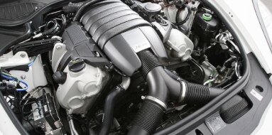
Suzuki F6B Specifications
| Engine Model: Suzuki F6B |
| Engine Type: 4-cycle inline 4-cylinder DOHC turbocharged liquid-cooled gasoline |
| Total Displacement: 40.1 cu.in (0.65 L) |
| Rated Engine Power: 63 Hp (47 kW) at 7000 rpm |
| Fuel System Type: Multi-point fuel injection |
____________________________________________________________________________________
The Suzuki F6B is a 658 cc, inline-four, turbocharged
gasoline engine produced during the early 1990s, representing a unique
engineering achievement within Japan’s Kei car class. As a member of the Suzuki
F engine family, the F6B stands apart as the only four-cylinder engine developed
to comply with the 660 cc displacement limit that defined the Kei vehicle
segment - a category otherwise dominated by three-cylinder power units such as
the Suzuki F6A. The engine combines a cast iron cylinder block with an aluminum
alloy DOHC cylinder head, featuring a turbocharger and intercooler to extract
maximum power from its diminutive displacement.
To achieve four-cylinder configuration within the strict capacity limit, Suzuki
retained the 65.0 mm bore dimension from the three-cylinder F6A while
significantly reducing the stroke to 49.6 mm, resulting in an ultra-short-stroke
design capable of exceptionally high engine speeds. The F6B was developed
exclusively for high-performance variants of the Suzuki Cervo Mode, where its
smooth operation, high-rpm character, and refined power delivery distinguished
it from the three-cylinder alternatives that prevailed in the Kei market.
The Suzuki F6B is a four-stroke, water-cooled, inline-four gasoline engine with
a total displacement of 658 cc (40.1 cu.in). The bore and stroke dimensions are
65.0 mm and 49.6 mm, respectively, creating an extremely oversquare
configuration that prioritizes high-rpm power delivery and enables the engine to
achieve a redline of approximately 9,000 rpm. The valvetrain employs a dual
overhead camshaft (DOHC) design with four valves per cylinder - two intake and
two exhaust - for a total of 16 valves. The camshafts are driven by a toothed
rubber timing belt, a critical maintenance component given the high-rpm
operating range.
Induction is provided by a turbocharger mounted to the exhaust manifold, with
compressed air routed through an intercooler to reduce intake charge temperature
before entering the throttle body. The fuel system utilizes multi-point fuel
injection (MPFI) managed by an engine control unit calibrated for the forced
induction application.
The compression ratio is set at a value suitable for turbocharged operation,
calibrated to balance power output with knock resistance under boost conditions.
Maximum power is rated at 47 kW (64 PS / 63 hp) at 7,000 rpm. Maximum torque is
produced at 3,500 rpm, with a rating of 82 Nm (60 lb-ft). The engine speed
limiter is set at approximately 9,000 rpm. The firing order is 1-2-4-3, an
arrangement selected to provide balanced primary and secondary forces in the
inline-four configuration.
The cylinder block is constructed from cast iron, a
material selected for its exceptional rigidity, acoustic damping properties, and
resistance to the elevated thermal and mechanical stresses associated with
turbocharged operation at high engine speeds. The block utilizes an open-deck
design where the cylinder bores are open at the top deck surface, allowing
efficient coolant flow around the upper cylinder region - a critical
consideration given the high specific output of this small-displacement engine.
The inline-four configuration incorporates five main bearings supporting a
forged steel or cast iron crankshaft. The crankshaft is of the fully
counterweighted design to minimize vibration at the high engine speeds
characteristic of this power unit. The connecting rods are constructed from
forged steel, specified to withstand the mechanical loads of sustained high-rpm
operation under boost.
Cylinder bores are precision-machined directly into the cast iron block, with a
plateau honed finish to optimize oil retention and piston ring sealing. The
water jacket surrounds the cylinders for effective heat transfer, with coolant
flow directed upward toward the cylinder head. The block’s compact dimensions
reflect the 658 cc displacement, with narrow bore spacing accommodating the four
cylinders within the physical constraints of the Kei car engine bay.
The cylinder head is manufactured from aluminum alloy,
providing reduced mass and enhanced heat dissipation compared to ferrous
alternatives - a critical factor in an engine designed for sustained high-rpm
operation. The dual overhead camshaft (DOHC) arrangement positions the intake
and exhaust camshafts within the head, supported by five bearing journals
machined directly into the head casting. The camshafts are driven by the timing
belt, with the intake camshaft incorporating the drive pulley.
Valves are arranged in a pent-roof combustion chamber configuration with a
narrow included valve angle to promote efficient flame propagation and
accommodate the high compression ratio suitable for turbocharged operation. The
valve diameters are proportioned to maximize airflow through the 65.0 mm bore.
Valve actuation is provided by bucket tappets that ride directly on the camshaft
lobes, allowing precise control of valvetrain geometry at high engine speeds.
Valve clearance is adjusted using shims positioned between the bucket tappet and
the valve stem.
The valve springs are of the double-coil type to ensure positive valve seating
and prevent valve float at the 9,000 rpm redline - a critical reliability
feature in this high-revving design. The combustion chamber is of the compact
pent-roof design with centrally located spark plugs to optimize flame
propagation. The cylinder head gasket is a multi-layer steel (MLS) design,
providing reliable sealing between the aluminum head and cast iron block under
the elevated cylinder pressures of turbocharged operation.
The fuel system is a multi-point electronic fuel
injection (MPFI) system managed by an engine control unit calibrated
specifically for the turbocharged application. An electric fuel pump mounted
within the fuel tank delivers fuel through a replaceable filter to a fuel rail
mounted on the intake manifold. The fuel pressure regulator maintains a constant
pressure across the injectors, referenced to intake manifold vacuum to maintain
a consistent pressure differential. The fuel injectors are solenoid-actuated,
with flow rates selected to support the power output under boost conditions.
The engine control unit calculates injector pulse width based on inputs from the
mass airflow sensor or manifold absolute pressure sensor, throttle position
sensor, coolant temperature sensor, intake air temperature sensor, crankshaft
position sensor, camshaft position sensors, and heated oxygen sensor. The ECU
employs closed-loop fuel control during part-throttle operation, adjusting fuel
delivery based on oxygen sensor feedback to maintain a stoichiometric air-fuel
ratio for optimal catalytic converter efficiency. During wide-open throttle
operation under boost, the system transitions to open-loop control, utilizing
pre-programmed fuel maps calibrated for maximum power output while maintaining
safe air-fuel ratios to prevent detonation.
The lubrication system is a full-flow, pressurized
circuit designed to support sustained high-rpm operation. A gear-type or
trochoid-type oil pump, mounted within the front timing case and driven directly
by the crankshaft, draws engine oil from a baffled aluminum sump through a
strainer screen before directing it through a full-flow spin-on oil filter. An
oil pressure relief valve maintains system pressure within the specified range.
The main oil gallery distributes pressurized oil to the crankshaft main
bearings, connecting rod bearings, camshaft bearings, and bucket tappets.
Piston cooling is accomplished through oil jets mounted in the crankcase,
directing a continuous spray to the underside of each piston crown - a feature
essential for managing thermal loads under sustained turbocharged operation at
high engine speeds. The total engine oil capacity, including the filter, is 3.5
L (3.7 qt) to 4.0 L (4.2 qt). Recommended oil viscosity is 5W-30, 5W-40, or
10W-40 with a high-quality synthetic formulation to withstand the thermal
stresses of turbocharged, high-rpm operation.
The cooling system operates as a pressurized,
thermostatically controlled water circulation circuit designed to manage the
thermal output of the turbocharged engine. A belt-driven centrifugal water pump,
mounted to the front of the cylinder block, circulates a mixture of water and
ethylene glycol antifreeze through the cylinder block, cylinder head,
turbocharger bearing housing, intercooler in water-to-air configurations, and
the main radiator. The thermostat is a wax-pellet type positioned on the coolant
outlet of the cylinder head, maintaining operating temperature within the range
of 85°C to 95°C (185°F to 203°F).
The radiator is a cross-flow aluminum construction sized to the compact Kei car
chassis, with sufficient cooling capacity for the turbocharged engine. An
electric cooling fan, controlled by a thermostatic switch or the engine control
unit based on coolant temperature, provides forced airflow during low-speed
operation or high ambient temperatures. An expansion tank allows for coolant
expansion and provides a point for air separation from the system. The total
cooling system capacity is 5.0 L (5.3 qt) to 5.5 L (5.8 qt) for the complete
system.
| Intake and Exhaust Systems |
Intake System: The intake manifold is constructed from
aluminum with short runner lengths optimized for high-rpm power delivery. The
turbocharger is a small-frame unit selected for rapid spool characteristics,
providing boost pressure suitable for the 658 cc displacement. The intercooler
reduces intake air temperatures under boost, enhancing charge density and
detonation resistance. The throttle body is electronically controlled or
cable-operated depending on the production year.
Exhaust System: The exhaust manifold is constructed from cast iron or tubular
steel, with the turbocharger mounted directly to the manifold outlet. A heated
oxygen sensor is mounted upstream of the turbocharger or in the downpipe to
provide feedback to the ECU for closed-loop fuel control. The exhaust system
includes a three-way catalytic converter to comply with Kei car emissions
regulations.
The ignition system utilizes a distributorless ignition
system with individual ignition coils or a wasted-spark configuration. The
engine control unit determines ignition timing based on inputs from the
crankshaft position sensor, camshaft position sensors, and knock sensor. The
knock sensor is a critical component in this turbocharged engine, allowing the
ECU to retard ignition timing under detonation conditions to protect the engine
while optimizing timing for maximum power under normal conditions.
The overall length, measured from the front accessory
drive to the flywheel mating face, is 520 mm (20.5 in). Width across the
cylinder head, intake manifold, and turbocharger assembly is 580 mm (22.8 in).
Height from the bottom of the oil sump to the top of the cylinder head cover is
620 mm (24.4 in). The dry weight of the engine, inclusive of the turbocharger,
intercooler, intake and exhaust manifolds, alternator, starter motor, and fuel
system components but without transmission or fluids, is 95 kg (209 lb).
The engine oil and filter must be replaced at intervals
not exceeding 5,000 km (3,107 mi) or six months under normal operation, with the
high-rpm, turbocharged design necessitating high-quality synthetic oil. The
timing belt is a critical maintenance item with a replacement interval of 60,000
km (37,282 mi) to 80,000 km (49,710 mi) depending on the market.
Due to the interference design and high-rpm operating range, the timing belt
tensioner and water pump must be replaced concurrently. Valve clearance
adjustment is required at intervals of 40,000 km (24,855 mi) to 60,000 km
(37,282 mi), with the cold clearance specification determined by the
shim-and-bucket design. The spark plugs require replacement every 30,000 km
(18,641 mi) for standard types.
The air filter element should be inspected at each oil change and replaced every
20,000 km (12,427 mi) depending on operating conditions. The fuel filter is a
replaceable in-line unit with a recommended service interval of 30,000 km
(18,641 mi). Coolant replacement is specified at 40,000 km (24,855 mi) or every
two years.
Cylinder Head Bolts: 25 Nm (18 lb-ft).
Main Bearing Cap Bolts: 35 Nm (26 lb-ft).
Connecting Rod Cap Bolts: 20 Nm (15 lb-ft).
Camshaft Bearing Caps: 10 Nm (7 lb-ft).
Flywheel Bolts: 60 Nm (44 lb-ft).
Crankshaft Pulley Bolt: 100 Nm (74 lb-ft).
Intake Manifold Bolts: 15 Nm (11 lb-ft).
Exhaust Manifold Nuts: 20 Nm (15 lb-ft).
Turbocharger Mounting Nuts: 25 Nm (18 lb-ft).
Oil Pan Bolts: 10 Nm (7 lb-ft).
Timing Belt Tensioner Bolt: 20 Nm (15 lb-ft).
Spark Plugs: 20 Nm (15 lb-ft).
Engine Mounting Brackets: 40 Nm (30 lb-ft).
The Suzuki F6B engine was produced exclusively for a
single high-performance Kei car model during its brief production run in the
early 1990s.
Suzuki Cervo Mode SR-Four (CN31S / CP31S, 1990-1997): The F6B served as the
exclusive power unit for the Cervo Mode SR-Four, a high-performance variant of
the Suzuki Cervo Kei car. This application represented the pinnacle of the Cervo
range, with the four-cylinder turbocharged engine delivering smooth power
delivery, high-rpm capability, and refined operation that distinguished it from
the three-cylinder F6A-equipped versions.
The engine was paired with a five-speed manual transmission and, in some
variants, all-wheel drive, creating a compact performance package unique within
the Kei class. The SR-Four designation indicated the combination of the 658 cc
four-cylinder engine with four-wheel drive, while the CP31S chassis code denoted
the front-wheel drive variant. Production of the F6B-equipped Cervo Mode
continued until 1997, after which Suzuki consolidated its Kei car engine
offerings around three-cylinder configurations.
____________________________________________________________________________________
| Car Engines Technical Specifications |
| Small Engines Technical Specifications |
| Industrial Engines Technical Specifications |
| Outboard Engines Technical Specifications |