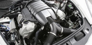
Subaru EJ22 Specifications
| Engine Model: Subaru EJ22 |
| Engine Type: 4-cycle 4-cylinder SOHC 16-valve liquid-cooled gasoline |
| Total Displacement: 135 cu.in (2.21 L) |
| Rated Engine Power: 130-142 Hp (97-106 kW) at 5800 rpm |
| Fuel System Type: Multi-point electronic fuel injection |
____________________________________________________________________________________
The Subaru EJ22 is a 2.2-liter, horizontally opposed
flat-four gasoline engine produced from 1989 to 2001. As part of Subaru’s EJ
engine family, the EJ22 gained a reputation as one of the most reliable
powerplants the company ever manufactured. Introduced as the primary engine for
the first-generation Legacy, it is distinguished by its thick cylinder walls and
robust block construction, features that made it highly resistant to the head
gasket issues that later affected larger-displacement EJ engines.
The EJ22 underwent a significant transition from Phase I to Phase II
architecture in the late 1990s, introducing changes to the valvetrain,
crankshaft thrust bearing placement, and engine management.
The EJ22 is a water-cooled, naturally aspirated flat-four engine with a
180-degree cylinder configuration. The horizontally opposed layout provides a
low center of gravity, inherent balance, and reduced vibration. The engine was
produced in two distinct phases: Phase I (1989-1998) with compression ratios
ranging from 9.5:1 to 9.7:1, and Phase II (1999-2001) with a higher 10.1:1
compression ratio.
Early Phase I engines utilized hydraulic lash adjusters and featured a
non-interference valvetrain, a design that prevented valve-to-piston contact in
the event of timing belt failure. Later Phase I engines and all Phase II
variants employed solid lifters and an interference valvetrain. A rare
turbocharged variant, the EJ22T, was produced for the 1991-1994 Legacy Sport
Sedan and Wagon, featuring a closed-deck block and piston oil squirters.
The EJ22 is a water-cooled, four-stroke, naturally aspirated gasoline engine
configured for longitudinal mounting in front-wheel-drive and all-wheel-drive
vehicle architectures. The engine was produced in Phase I and Phase II
configurations with differing compression ratios, valvetrain designs, and
interference characteristics.
Engine Type: Horizontally opposed flat-4, 4-cycle, water-cooled, naturally
aspirated.
Displacement: 2,212 cc (135.0 cu.in).
Bore and Stroke: 96.9 mm (3.81 in) x 75.0 mm (2.95 in).
Firing Order: 1-3-2-4.
Idle Speed: 700 ± 100 rpm.
Engine Redline: 6,500 rpm.
Phase I (1989-1998)
Compression Ratio: 9.5:1 (early) to 9.7:1 (late).
Valvetrain: SOHC, 16-valve, hydraulic lash adjusters (early) or solid lifters
(late 1997+).
Maximum Power: 97-101 kW (130-135 hp) at 5,800 rpm.
Maximum Torque: 186-190 Nm (137-140 lb-ft) at 4,400 rpm.
Phase II (1999-2001)
Compression Ratio: 10.1:1.
Valvetrain: SOHC, 16-valve with belt drive; solid lifters with screw-type
adjusters.
Maximum Power: 106 kW (142 hp) at 5,600 rpm.
Maximum Torque: 202 Nm (149 lb-ft) at 3,600 rpm.
The cylinder block is constructed from aluminum alloy
and incorporates cast iron cylinder liners. The horizontally opposed
configuration places the cylinders in two banks arranged 180 degrees apart, with
the crankshaft located centrally. This design provides a low center of gravity
and inherent primary balance, eliminating the need for balance shafts. The EJ22
utilizes an open-deck block design where the cylinder bores are partially
surrounded by the water jacket at the top deck surface. Due to the smaller bore
of the EJ22 compared to the EJ25 while sharing similar casting dimensions, the
cylinder walls are significantly thicker, contributing to the engine’s
structural integrity and resistance to head gasket failure.
The block incorporates five main bearing webs with two-bolt main bearing caps.
The crankshaft is supported by five bearings. The Phase I engine features a
thrust bearing located at the center main bearing, while the Phase II engine
relocates the thrust bearing to the rear main bearing position, a change that
altered the bellhousing bolt pattern from four to eight bolts. The turbocharged
EJ22T variant utilizes a fully closed-deck block with additional material around
the cylinder bores and integrated piston oil squirters for enhanced durability
under forced induction.
Block Material: Aluminum alloy with cast iron cylinder liners
Bore Diameter (finished): 96.9 mm (3.81 in)
Main Bearing Caps: Cast iron, two-bolt design
Cylinder Bore Deformation Limit: 0.05 mm (0.0020 in)
The cylinder heads are manufactured from aluminum
alloy, with separate heads for each cylinder bank. The SOHC valvetrain actuates
sixteen valves - four valves per cylinder - through a system of rocker arms.
Early Phase I engines utilize hydraulic lash adjusters (HLAs) that automatically
maintain zero valve clearance. Late Phase I engines (1997-1998) and Phase II
engines employ solid lifters with screw-type adjusters requiring periodic manual
valve clearance adjustment.
The camshafts are driven by a reinforced rubber timing belt from the crankshaft,
with an automatic spring-loaded tensioner maintaining belt tension. The
combustion chambers are of a compact pent-roof design with centrally located
spark plugs. The non-interference valvetrain of early Phase I engines provides a
critical safety margin: if the timing belt fails, valves and pistons do not
contact, preventing internal damage.
Head Material: Aluminum alloy
Valve Configuration: SOHC, 4 valves per cylinder with rocker arms; hydraulic
lash adjusters (early Phase I) or solid lifters (late Phase I and Phase II).
Valve Diameter (Intake): 36.0 mm (1.42 in).
Valve Diameter (Exhaust): 32.0 mm (1.26 in).
Valve Stem Diameter: 6.0 mm (0.24 in).
Valve Seat Angle: 45 degrees.
The EJ22 employs a multi-point electronic fuel
injection system. Four fuel injectors are mounted in the intake manifold,
positioned to spray fuel directly onto the back of each intake valve. The port
injection design provides excellent air-fuel mixture preparation and throttle
response. Early Phase I engines utilized a mass airflow sensor-based system,
while later Phase I and Phase II engines transitioned to a speed-density system
using manifold absolute pressure (MAP) sensing.
A fuel pump assembly located within the fuel tank supplies pressurized fuel to a
fuel rail that distributes fuel evenly to all four injectors. The engine control
unit (ECU) calculates injection pulse width based on input from the airflow
sensor or MAP sensor, throttle position sensor, coolant temperature sensor,
crankshaft position sensor, and oxygen sensor feedback. The Phase II engine
utilizes a more advanced ECU with improved fuel and ignition maps calibrated for
the higher 10.1:1 compression ratio.
Injection Type: Multi-point electronic fuel injection (port injection)
Fuel Pressure: 255-294 kPa (37.0-42.6 psi)
Fuel Injector Resistance: 12.0-16.0 Ohms
Fuel Requirement: 87 octane (Research Octane Number 91) minimum
Fuel Cutoff: 6,500 rpm
The lubrication system is a fully pressurized, wet-sump
design utilizing a gear-type oil pump mounted to the front of the crankshaft.
The oil pump draws lubricant from the stamped steel oil pan through a mesh
strainer and circulates it through a full-flow, replaceable oil filter before
entering the main oil gallery. From the gallery, pressurized oil is distributed
to the crankshaft main bearings, connecting rod bearings, camshaft bearings,
rocker arm assemblies, hydraulic lash adjusters (on early engines), and timing
belt tensioner.
A pressure relief valve integrated into the oil pump maintains system pressure
within operational limits. The oil pump front seal and camshaft seals are common
leak points on high-mileage engines. A plastic oil separator plate mounted at
the rear of the engine is prone to leakage and is often replaced with an
aluminum version during service.
Oil Type: SAE 5W-30, 10W-30, or 10W-40 (API SG, SH, or higher)
Oil Capacity (with filter): 4.0-4.5 liters (4.2-4.8 US qt)
Oil Pressure (at 3,000 rpm): 294-392 kPa (42.6-56.9 psi)
Oil Pump Type: Gear-type, crankshaft-driven
Oil Filter Type: Spin-on, full-flow
The cooling system is a pressurized, liquid-cooled
design employing a cross-flow aluminum radiator with an electric cooling fan. A
centrifugal-type water pump, driven by the timing belt, circulates coolant
through the engine block, cylinder heads, heater core, and throttle body warmer.
A wax-pellet thermostat regulates coolant flow to maintain optimal operating
temperature, with a bypass circuit that allows the engine to warm rapidly.
The cooling system is designed to provide uniform cooling across both cylinder
banks. The Phase I engine is less prone to head gasket failure than later EJ25
engines, attributed to the thicker cylinder walls and more robust head gasket
design.
Coolant Type: Ethylene-glycol based antifreeze with corrosion inhibitors
Coolant Capacity: 5.5-6.5 liters (5.8-6.9 US qt) (variant dependent)
Thermostat Opening Temperature: 82-86 °C (180-187 °F)
Thermostat Full-Open Temperature: 95 °C (203 °F)
Radiator Cap Pressure: 88-108 kPa (12.8-15.7 psi)
Water Pump Type: Centrifugal, timing belt-driven
Ignition System: Distributor-based ignition system on
early Phase I engines. Later Phase I and Phase II engines utilize a
distributorless ignition system with individual ignition coils mounted directly
over each spark plug or a waste-spark system with two coils serving four
cylinders. The system incorporates a crankshaft position sensor and camshaft
position sensor for precise ignition timing control.
Intake System: Cast aluminum intake manifold with a two-piece design
incorporating a plenum chamber and individual runners. The intake system
incorporates an air cleaner housing with a dry-type paper filter element. A
throttle body with a mechanically operated butterfly valve controls airflow into
the engine.
Exhaust System: Cast iron exhaust manifold with individual runners per cylinder
bank collecting into a single downpipe. A heated oxygen sensor is mounted
upstream of the catalytic converter for fuel trim feedback.
Timing Drive: A reinforced rubber timing belt with integral teeth drives the
camshafts from the crankshaft sprocket. The belt also drives the water pump. An
automatic spring-loaded tensioner maintains belt tension. The timing belt is a
scheduled maintenance item with a defined replacement interval. Early
non-interference engines provide a safety margin against belt failure.
Overall Length: 700 mm (27.6 in)
Overall Width: 860 mm (33.9 in)
Overall Height: 600 mm (23.6 in)
Dry Weight (complete engine): 125-135 kg (276-298 lb)
Oil Change Interval: 10,000 km (6,200 mi) under normal
driving conditions.
Oil Change Interval: 5,000 km (3,100 mi) under severe conditions.
Oil Filter Change: At every oil change.
Timing Belt Replacement: 100,000 km (60,000 mi) or 5 years.
Engine Coolant Replacement: 40,000 km (25,000 mi) or 2 years.
Spark Plug Replacement: 30,000 km (18,600 mi) for standard plugs.
Spark Plug Replacement: 100,000 km (60,000 mi) for platinum plugs.
Spark Plug Type: NGK BKR6E-11 or equivalent.
Spark Plug Gap: 1.0-1.1 mm (0.039-0.043 in).
Drive Belt (Accessory) Inspection: Every 10,000 km (6,200 mi) for tension,
cracking, and glazing.
Air Filter Replacement: 20,000 km (12,500 mi) or as indicated by inspection.
Fuel Filter Replacement: 40,000 km (25,000 mi) for external filter types.
Valve Clearance Adjustment (Solid Lifters): Inspect and adjust every 100,000 km
(60,000 mi).
Valve Clearance Intake: 0.20-0.24 mm (0.0079-0.0094 in) cold.
Valve Clearance Exhaust: 0.24-0.28 mm (0.0094-0.0110 in) cold.
Idle Speed Adjustment: 700 ± 100 rpm with no electrical or accessory load.
Cylinder Head Bolts (M10 x 1.25), 1st pass: 20-25 Nm
(15-18 lb-ft).
Cylinder Head Bolts (M10 x 1.25), 2nd pass: 50-55 Nm (37-41 lb-ft).
Main Bearing Cap Bolts (M10 x 1.25): 45-50 Nm (33-37 lb-ft).
Connecting Rod Cap Bolts (M8 x 1.0): 25-28 Nm (18-21 lb-ft).
Camshaft Bearing Cap Bolts (M8 x 1.25): 18-22 Nm (13-16 lb-ft).
Rocker Arm Shaft Bolts (M8 x 1.25): 18-22 Nm (13-16 lb-ft).
Intake Manifold Bolts (M8 x 1.25): 16-20 Nm (12-15 lb-ft).
Exhaust Manifold Nuts (M8 x 1.25): 16-20 Nm (12-15 lb-ft).
Spark Plugs: 18-22 Nm (13-16 lb-ft).
Oil Pan Bolts (M6 x 1.0): 8-10 Nm (71-89 lb-in).
Water Pump Bolts (M6 x 1.0): 8-10 Nm (71-89 lb-in).
Timing Belt Tensioner Bolt (M8 x 1.25): 18-22 Nm (13-16 lb-ft).
Crankshaft Pulley Bolt (M14 x 1.5): 130-140 Nm (96-103 lb-ft).
Flywheel / Drive Plate Bolts (M10 x 1.25): 70-75 Nm (52-55 lb-ft).
The Subaru EJ22 engine was utilized across a broad
range of Subaru passenger vehicles in North American, Australian, and other
markets throughout its production period.
Subaru Legacy / Liberty: 1989-1999 model years.
Subaru Impreza: 1995-2001 model years (L, Outback Sport, and base trims).
Subaru Legacy Sport Sedan / Wagon: 1991-1994 model years (EJ22T turbocharged
variant).
Subaru Outback: Early model years with 2.2-liter engine (1995-1996).
____________________________________________________________________________________
| Car Engines Technical Specifications |
| Small Engines Technical Specifications |
| Industrial Engines Technical Specifications |
| Outboard Engines Technical Specifications |