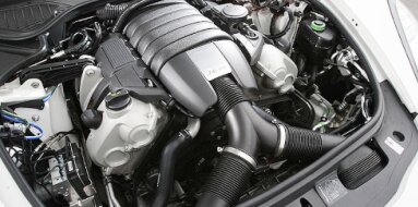
Subaru EJ16 Specifications
| Engine Model: Subaru EJ16 |
| Engine Type: 4-cycle 4-cylinder SOHC 16-valve liquid-cooled gasoline |
| Total Displacement: 97.5 cu.in (1.59 L) |
| Rated Engine Power: 90-100 Hp (66-74 kW) at 6000 rpm |
| Fuel System Type: Multi-point electronic fuel injection |
____________________________________________________________________________________
The Subaru EJ16 represents a downsized variant within
the extensively developed EJ engine family, sharing its fundamental all-aluminum
construction with larger-displacement siblings. The horizontally opposed
configuration provides a low center of gravity, contributing to vehicle
stability while maintaining a compact engine bay footprint. The single overhead
camshaft (SOHC) valvetrain with 16 valves offers a balance of mechanical
simplicity and efficient cylinder filling.
The Phase II redesign introduced significant internal modifications including a
relocated thrust bearing at the number five main bearing position and an offset
crankshaft design, reducing frictional losses and enabling a higher compression
ratio for improved thermal efficiency. The interference valvetrain design places
critical importance on timing belt maintenance, as belt failure results in
piston-to-valve contact.
Multi-port fuel injection with either mass airflow or manifold absolute pressure
sensing provides reliable fuel delivery across varied operating conditions. The
engine’s durability is well established, though its modest power output,
particularly when paired with all-wheel drive and automatic transmission,
results in performance characteristics suited primarily to urban and highway
cruising rather than spirited driving.
Engine Type: Horizontally opposed 4-cylinder (flat-four), 4-cycle, naturally
aspirated.
Displacement: 1,597 cc (97.5 cu.in).
Bore x Stroke: 87.9 mm x 65.8 mm (3.46 in x 2.59 in).
Compression Ratio (Phase I): 9.4:1.
Compression Ratio (Phase II): 9.7:1 to 10.0:1.
Firing Order: 1-3-2-4.
Maximum Power (Phase I): 90-95 hp (66-70 kW) @ 6,000 rpm.
Maximum Power (Phase II): 95-100 hp (70-74 kW) @ 5,600 rpm.
Maximum Torque (Phase I): 137 Nm (101 lb-ft) @ 3,600 rpm.
Maximum Torque (Phase II): 143 Nm (105 lb-ft) @ 3,600 rpm.
Idle Speed: 700 ± 50 rpm.
Valvetrain: SOHC, 16 valves (4 valves per cylinder).
Belt-driven camshaft with mechanical or hydraulic lash adjusters depending on
production period.
The cylinder block is constructed from aluminum alloy
with cast iron cylinder liners, providing a lightweight structure with durable
wear surfaces. The horizontally opposed configuration positions two banks of two
cylinders opposite each other, with the crankshaft located at the centerline of
the block. The block features an open-deck design at the cylinder head
interface, allowing efficient coolant flow around each cylinder bore. Five main
bearings support the crankshaft.
Phase I engines locate the thrust bearing at the number three main bearing
position. Phase II engines relocate the thrust bearing to the number five main
bearing position at the rear of the block, improving crankshaft stability and
reducing frictional losses. The water jacket is cast integrally with the block,
surrounding each cylinder with coolant passages. The engine mounting points are
positioned on the sides of the block to accommodate the longitudinal engine
orientation in Subaru chassis.
The cylinder head is manufactured from aluminum alloy,
with separate heads for each cylinder bank. Each head incorporates a SOHC
configuration with the camshaft supported by four bearings. The 16 valves are
arranged with four valves per cylinder in a pent-roof combustion chamber design.
Valve actuation is achieved via rocker arms operating from the camshaft.
Phase I engines utilize mechanical lash adjusters requiring periodic valve
clearance inspection. Phase II engines incorporate hydraulic lash adjusters,
eliminating manual adjustment requirements. The intake ports are designed with a
swirl-inducing geometry to enhance air-fuel mixing. The exhaust ports are
integrated into the cylinder head casting with a compact manifold interface. The
camshaft drive sprocket is mounted at the front of each head, driven by the
timing belt.
The engine is equipped with a multi-point fuel
injection (MPFI) system. Individual fuel injectors are mounted in the intake
manifold runners, positioned to direct fuel toward the intake valves. The fuel
system operates at a regulated pressure of approximately 2.5-3.0 bar (36-44
psi). Early Phase I engines utilize a mass airflow (MAF) sensor mounted upstream
of the throttle body to measure intake air volume.
Later Phase II engines transition to a manifold absolute pressure (MAP) sensor
system, which improves reliability by eliminating the hot-wire contamination
issues associated with MAF sensors. An engine control unit (ECU) manages
injection duration and ignition timing based on sensor inputs. The intake
manifold is constructed from composite material or aluminum depending on
production period, with runner lengths tuned to enhance torque in the low-to-mid
rpm range.
The lubrication system is a pressurized, wet-sump
configuration designed for the horizontally opposed engine layout. A gear-type
oil pump, mounted to the front of the crankshaft, circulates engine oil through
a full-flow disposable filter. The oil pump rotor is driven directly by the
crankshaft nose. Oil galleries within the block and cylinder heads supply
pressurized oil to the crankshaft main bearings, connecting rod bearings,
camshaft bearings, and valve actuation components.
The horizontally opposed configuration requires careful oil drainback design,
with the cylinder heads incorporating oil return passages to prevent oil
accumulation in the valve covers. Total oil capacity, including the filter, is
3.8 liters (4.0 qt).
The cooling system is a pressurized, water-cooled
design engineered for the horizontally opposed engine configuration. A
belt-driven water pump, mounted to the front of the engine block, circulates
coolant through the cylinder block, both cylinder heads, and the radiator. The
water pump is driven by the same timing belt that operates the camshafts.
A wax-type thermostat, beginning to open at 78-82°C (172-180°F), regulates
coolant flow to maintain optimal operating temperatures. The system utilizes a
cross-flow radiator with an electric cooling fan controlled by the ECU based on
coolant temperature and air conditioning operation. An expansion tank allows for
coolant expansion and air separation. Total coolant capacity is 5.5 liters (5.8
qt).
Ignition System: The EJ16 utilizes a distributor-less
ignition system with individual ignition coils mounted near the spark plugs or a
waste-spark coil pack configuration depending on production period. A crankshaft
position sensor mounted at the rear of the engine provides timing information to
the ECU. Knock sensor feedback allows the ECU to adjust ignition timing for
optimal performance under varying fuel quality.
Timing System: The camshafts are driven by a rubber-reinforced timing belt. The
belt engages the crankshaft sprocket and routes around tensioner and idler
pulleys to drive both cylinder head camshaft sprockets. The belt also drives the
water pump. The engine is an interference design; timing belt failure results in
piston-to-valve contact, causing extensive engine damage.
Emission Control: The engine incorporates a closed-loop emission control system
featuring a three-way catalytic converter, exhaust gas recirculation (EGR)
valve, and positive crankcase ventilation (PCV). A heated oxygen sensor mounted
in the exhaust downpipe provides feedback for closed-loop air-fuel ratio
control. The system is calibrated to meet Euro 2 and Euro 3 emission standards
depending on the model year.
Electrical System: The charging system consists of a 12-volt, 75-90 amp
alternator. The starter motor is a 1.0 kW (1.3 hp) unit.
Accessory Drive: The alternator, power steering pump, and air conditioning
compressor are driven by a single serpentine belt from the crankshaft pulley. An
automatic tensioner maintains consistent belt tension without periodic
adjustment.
Dry Weight: 105 kg (231 lb).
Overall Length (from accessory drive to flywheel): 580 mm (22.8 in).
Overall Width: 620 mm (24.4 in).
Overall Height: 510 mm (20.1 in).
Engine Oil Capacity (with filter): 3.8 liters (4.0 qt).
Engine Oil Specification: SAE 5W-30, 10W-30, or 10W-40 meeting API SL or higher.
Engine Oil Pressure (at idle): Minimum 0.8 bar (12 psi).
Engine Oil Pressure (at 3,000 rpm): 3.5-4.5 bar (51-65 psi).
Coolant Capacity: 5.5 liters (5.8 qt).
Coolant Specification: Ethylene glycol-based antifreeze with corrosion
inhibitors.
Spark Plug Type: NGK BKR6E-11 or equivalent.
Spark Plug Gap: 1.0-1.1 mm (0.039-0.043 in).
Ignition Timing: 10°-12° BTDC at idle with diagnostic terminals shorted.
Intake Valve Clearance (Cold, Phase I Mechanical Lifters): 0.20-0.25 mm
(0.008-0.010 in).
Exhaust Valve Clearance (Cold, Phase I Mechanical Lifters): 0.25-0.30 mm
(0.010-0.012 in).
Valve Clearance Inspection Interval (Phase I): Every 40,000 km (25,000 miles).
Valve Clearance (Phase II Hydraulic Lifters): Not adjustable; no service
interval required.
Timing Belt Replacement Interval: Every 100,000 km (62,000 miles) or 5 years.
Idle Speed: 700 ± 50 rpm.
Fuel Pressure: 2.5-3.0 bar (36-44 psi).
Compression Pressure: Standard: 12.0-14.0 bar (174-203 psi).
Compression Pressure: Minimum allowable: 10.0 bar (145 psi).
Compression Pressure: Maximum variation between cylinders: 1.5 bar (22 psi).
Cylinder Head Bolts (M11), Stage 1: 30 Nm (22 lb-ft).
Cylinder Head Bolts (M11), Stage 2: 60 Nm (44 lb-ft).
Main Bearing Cap Bolts: 55-60 Nm (41-44 lb-ft).
Connecting Rod Cap Nuts: 35-40 Nm (26-30 lb-ft).
Camshaft Bearing Cap Bolts: 15-18 Nm (11-13 lb-ft).
Camshaft Sprocket Bolts: 50-55 Nm (37-41 lb-ft).
Flywheel Bolts: 65-70 Nm (48-52 lb-ft).
Crankshaft Pulley Bolt: 120-130 Nm (89-96 lb-ft).
Intake Manifold Nuts: 18-22 Nm (13-16 lb-ft).
Exhaust Manifold Nuts: 20-25 Nm (15-18 lb-ft).
Spark Plugs: 20-25 Nm (15-18 lb-ft).
Oil Pan Bolts: 8-10 Nm (6-7 lb-ft).
Valve Cover Bolts: 6-8 Nm (4-6 lb-ft).
Timing Belt Tensioner Bolt: 20-25 Nm (15-18 lb-ft).
Water Pump Bolts: 10-12 Nm (7-9 lb-ft).
Engine Mount (Bracket to Block): 45-50 Nm (33-37 lb-ft).
Engine Mount (Through Bolt): 55-60 Nm (41-44 lb-ft).
The Subaru EJ16 engine was utilized primarily in the
Impreza chassis across multiple generations, with front-wheel drive and
all-wheel drive configurations offered depending on market.
Subaru Impreza (GC3 / GF3): 1993-2000, the EJ16 served as a base engine option
for the first-generation Impreza in European, Australian, and Asian markets,
available in both sedan and wagon body styles.
Subaru Impreza (GC4 / GF4): Front-wheel drive variants of the first-generation
Impreza received the EJ16 as a standard powerplant in markets where all-wheel
drive was optional.
Subaru Impreza (GD3 / GG3): 2001-2006, the second-generation Impreza continued
to utilize the EJ16 as a base engine in European and Middle Eastern markets,
with power output calibrated to meet Euro 3 emission standards.
Subaru Leone: Late production variants of the Leone in select export markets
received the EJ16 as a transitional engine prior to the full introduction of the
Impreza lineup.
____________________________________________________________________________________
| Car Engines Technical Specifications |
| Small Engines Technical Specifications |
| Industrial Engines Technical Specifications |
| Outboard Engines Technical Specifications |