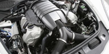
Mitsubishi 8M20 Specifications
| Engine Model: Mitsubishi 8M20 |
| Engine Type: 4-cycle 8-cylinder V-block OHV 16-valve liquid-cooled diesel |
| Total Displacement: 1225 cu.in (20.1 L) |
| Rated Engine Power: 385-400 Hp (283-294 kW) at 2000 rpm |
| Fuel System Type: Direct injection |
____________________________________________________________________________________
The Mitsubishi 8M20 is a 20-liter, naturally aspirated
V8 diesel engine that formed the backbone of heavy-duty commercial transport for
Mitsubishi Fuso during the late 20th century. Developed as part of the 8M2
series, this engine was engineered for applications demanding exceptional
durability, high displacement, and operational simplicity rather than forced
induction.
Its architecture prioritizes mechanical robustness and sustained high-load
performance, making it a preferred power unit for Mitsubishi Fuso Super Great
heavy-duty trucks, as well as premium highway coaches such as the Aero Queen and
Aero King.
The engine operates on a four-stroke cycle with a 90-degree V8 configuration,
utilizing a direct injection combustion system. Distinguished by its substantial
displacement and naturally aspirated induction, the 8M20 was designed to deliver
reliable power across extended service intervals, with a focus on ease of
maintenance and resistance to thermal stress in demanding line-haul
applications.
Displacement: 20,089 cc (1,225 cu.in)
Bore x Stroke: 142 mm x 158 mm (5.59 in x 6.22 in)
Dry Weight: 1,250 kg (2,755 lbs)
Power: 283-294 kW (385-400 HP)
Torque: 1,353-1,470 Nm (998-1,084 lb-ft)
Compression Pressure: 2.75 MPa (398 psi)
The Mitsubishi 8M20 is a naturally aspirated, water-cooled, four-stroke diesel
engine configured in a 90-degree V8 layout. Total displacement measures 20,089
cc, derived from a bore of 142 mm and a stroke of 158 mm. The valvetrain employs
an overhead valve (OHV) design with two valves per cylinder - one intake and one
exhaust - actuated by pushrods and rocker arms from a centrally positioned
camshaft within the cylinder block.
The combustion system utilizes direct injection, where fuel is injected directly
into the combustion chamber formed in the piston crown. The compression ratio is
fixed at 18.0:1. The firing order is 1-2-7-3-4-5-6-8, ensuring balanced primary
and secondary forces across the 90-degree V-angle.
Power output for the 8M20 is rated between 385 and 400 hp (283 to 294 kW) at
2,200 rpm, depending on the specific calibration and vehicle application.
Maximum torque is developed between 1,200 and 1,400 rpm, with figures ranging
from 1,353 to 1,470 Nm (998 to 1,084 lb-ft). The standard compression pressure
is specified at 2.75 MPa (398 psi) measured at a cranking speed of 200 rpm with
the engine at operating temperature.
The cylinder block is constructed from high-strength
cast iron, utilizing a deep-skirt design where the block walls extend below the
crankshaft centerline to maximize rigidity under heavy combustion loads. The V8
configuration features a 90-degree bank angle, providing a low center of gravity
and balanced packaging for chassis installation. The block incorporates siamesed
cylinder bores - adjacent cylinders share common walls - to enhance structural
integrity and reduce overall block length. Each cylinder bore is fitted with
replaceable, centrifugally cast wet-type cylinder liners.
These liners are precision-machined and hardened to withstand the high ring
pressures of direct-injection combustion, and their wet design allows direct
contact with coolant for efficient heat transfer. The crankshaft is supported by
five main bearings, each with a wide bearing area to distribute loads from the
eight cylinders evenly. The crankcase area is reinforced with transverse
bulkheads to resist twisting forces encountered during high-torque operation.
Two separate cylinder heads are used, one for each
cylinder bank, manufactured from cast iron to match the thermal expansion
characteristics of the block and to provide superior sealing under high
combustion pressures. Each head incorporates a direct injection pre-combustion
chamber design, where the injector nozzle and glow plug are positioned to direct
fuel into a carefully shaped recess within the cylinder head. The valvetrain is
of the overhead valve configuration with two valves per cylinder. Valves are
arranged in a single row per cylinder bank and are actuated by a camshaft
located within the cylinder block.
Pushrods transmit motion from the camshaft to individually mounted rocker arms,
which pivot on a rocker shaft to open the valves. Valve springs are of the
double-coil type to ensure positive valve seating under all operating
conditions. Valve seat inserts are made from heat-resistant alloy and are
replaceable. The cylinder head gasket is a multi-layer steel design with
precision embossing to accommodate the interface between the cast iron head and
block while maintaining consistent clamp load across the length of each cylinder
bank.
The fuel system is a mechanically governed direct
injection system centered on a Bosch-type in-line injection pump. This pump is
mounted longitudinally on the engine and is driven directly from the timing gear
train. It features a separate plunger and barrel assembly for each cylinder,
delivering precisely metered fuel at high pressure to the injection nozzles. The
injection timing is mechanically controlled and adjustable via shims or timing
advance mechanisms. Fuel injection nozzles are of the multi-hole type, designed
to create a finely atomized spray pattern optimized for the direct injection
combustion chamber.
A mechanical governor integrated into the injection pump controls engine speed
under varying loads, maintaining stable operation from idle to rated speed. A
supply pump draws fuel from the chassis-mounted tank, delivering it through a
primary filter and a secondary full-flow filter before entering the injection
pump. Excess fuel not used for combustion is returned to the fuel tank through a
return line, providing cooling for the injection system components.
The lubrication system operates as a forced-feed,
full-pressure circuit utilizing a gear-type oil pump mounted within the timing
gear case. The pump is driven directly by the crankshaft, ensuring immediate oil
pressure upon engine start. Oil is drawn from a large-capacity steel sump
through a strainer screen before entering the pump. The pressurized oil is
directed through a full-flow spin-on oil filter, with an integral bypass valve
to maintain circulation in the event of filter restriction. A water-cooled oil
cooler is integrated into the lubrication circuit to regulate oil temperature
during extended high-load operation.
The main oil gallery distributes pressurized oil to the crankshaft main
bearings, connecting rod bearings, camshaft bearings, and the timing gears.
Piston cooling is accomplished via oil jets directed at the underside of each
piston crown, a critical feature for managing thermal loads in a naturally
aspirated diesel of this displacement. Oil capacity ranges from 35 to 45 L
depending on the depth of the oil pan specified for the chassis application.
The cooling system is a pressurized, thermostatically
controlled water circulation system designed to manage the substantial thermal
output of the 20-liter V8. A belt-driven centrifugal water pump mounted at the
front of the engine circulates coolant through the cylinder block, cylinder
heads, and the main radiator. Coolant flow is directed first to the cylinder
block to provide even cooling around the wet-type cylinder liners before
ascending into the cylinder heads. The thermostat housing contains a wax-pellet
thermostat that maintains coolant temperature within the optimal operating range
of 80 to 90 C.
The radiator is a cross-flow type with large cooling capacity, constructed with
copper or aluminum cores depending on the vehicle specification. A viscous-drive
fan provides variable cooling airflow, reducing parasitic losses when maximum
cooling is not required. An expansion tank allows for coolant expansion and
provides a point for air separation from the system. Coolant conditioner filters
are incorporated in many installations to maintain proper chemical balance and
prevent cavitation erosion around cylinder liners.
| Intake and Exhaust Systems |
Intake System: The intake manifold is a cast iron
design with separate passages for each cylinder bank, fed from a centrally
mounted air cleaner housing. As a naturally aspirated engine, intake air is
drawn solely by atmospheric pressure through a large-capacity dry-type air
filter. The intake runners are tuned to optimize volumetric efficiency across
the operating range.
Exhaust System: Exhaust manifolds are constructed from heavy-wall cast iron to
resist thermal fatigue and are mounted to the outer side of each cylinder head.
The manifolds collect exhaust gases from four cylinders per bank and direct them
to a single exhaust outlet for connection to the vehicle’s exhaust piping.
Starting System: An electric starter motor with
reduction gearing is mounted to the flywheel housing, designed to deliver high
cranking torque for cold starts and to overcome the high compression pressure of
the direct injection diesel. The system is supported by heavy-duty batteries
with sufficient cold-cranking capacity.
Governor: A mechanical all-speed governor is integrated into the injection pump,
maintaining engine speed from idle to maximum rated rpm under varying load
conditions. This governor also incorporates a torque rise characteristic to
provide increased power under momentary overload conditions.
The overall length, measured from the front accessory
drive to the flywheel housing face, is 1,550 mm (61.0 in). Width across the
cylinder heads and exhaust manifolds measures 1,050 mm (41.3 in). Height from
the bottom of the oil pan to the top of the cylinder heads is 1,250 mm (49.2
in). The dry weight of the engine, fully dressed with the flywheel, injection
pump, starter, and alternator but without transmission or fluids, is 1,250 kg
(2,755 lb).
Maintenance intervals for the 8M20 are defined by
operating hours or distance traveled, with heavy-duty applications typically
following a structured schedule. The engine oil must conform to API
classification CD or higher for naturally aspirated diesel service, with
viscosity selected based on ambient operating temperatures. The oil change
interval is generally specified at 10,000 km (6,214 mi) for severe service or
every 250 operating hours, accompanied by replacement of the full-flow oil
filter.
The fuel filter elements - both primary and secondary - require replacement at
20,000 km (12,427 mi) intervals or as indicated by fuel system performance.
Valve clearance adjustment is required at regular intervals due to the
mechanical valvetrain; the procedure is performed with the engine cold.
Coolant requires periodic testing for nitrite and inhibitor levels, with full
replacement recommended every two years or 50,000 km (31,069 mi). The cylinder
liners protrude slightly above the cylinder block deck, and liner height must be
verified during any cylinder head removal to ensure proper gasket sealing.
Cylinder Head Bolts: 175 Nm (129 lb-ft).
Main Bearing Cap Bolts: 115 Nm (85 lb-ft).
Connecting Rod Cap Bolts: 115 Nm (85 lb-ft).
Flywheel Bolts: 315 Nm (232 lb-ft).
Crankshaft Pulley Bolt: 450 Nm (332 lb-ft).
Camshaft Thrust Plate Bolts: 20 Nm (15 lb-ft).
Rocker Arm Shaft Bracket Bolts: 45 Nm (33 lb-ft).
Injection Pump Mounting Nuts: 40 Nm (30 lb-ft).
Injection Nozzle Holder: 70 Nm (52 lb-ft).
Oil Pan Bolts: 20 Nm (15 lb-ft).
Timing Gear Cover Bolts: 25 Nm (18 lb-ft).
The Mitsubishi 8M20 engine was primarily deployed in
heavy-duty commercial vehicles requiring sustained high power output and
exceptional durability under full-load conditions.
Mitsubishi Fuso Super Great: The 8M20 served as a flagship power unit for the
Super Great heavy-duty truck series, utilized in tractor units for long-haul
transport, rigid chassis configurations for freight distribution, and
specialized heavy equipment carriers where naturally aspirated reliability was
prioritized over turbocharged complexity.
Mitsubishi Fuso Aero Queen: This engine was installed in the Aero Queen premium
highway coach series, providing the thermal stability and low-end torque
necessary for sustained high-speed passenger transport with full loads.
Mitsubishi Fuso Aero King: The Aero King, a tri-axle high-deck coach designed
for long-distance intercity routes, utilized the 8M20 for its combination of
displacement-derived torque and mechanical simplicity, ensuring operational
reliability in demanding tour and charter applications.
Mitsubishi Fuso Heavy-Duty Chassis: The engine was also offered in heavy-duty
truck chassis configured for specialized applications such as concrete mixer
trucks, dump trucks, and fire apparatus, where the naturally aspirated engine’s
linear power delivery and robust cooling system proved advantageous.
____________________________________________________________________________________
| Car Engines Technical Specifications |
| Small Engines Technical Specifications |
| Industrial Engines Technical Specifications |
| Outboard Engines Technical Specifications |