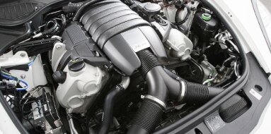
Mitsubishi 6A13TT Specifications
| Engine Model: Mitsubishi 6A13TT |
| Engine Type: 4-cycle 6-cylinder SOHC 24-valve turbocharged liquid-cooled gasoline |
| Total Displacement: 152.4 cu.in (2.49 L) |
| Rated Engine Power: 276 Hp (206 kW) at 5500 rpm |
| Fuel System Type: Multi-point electronic fuel injection |
____________________________________________________________________________________
The Mitsubishi 6A13TT is a 2.5-liter, twin-turbocharged
V6 engine produced by Mitsubishi Motors from 1996 through the early 2000s. This
power unit represents the pinnacle of the 6A engine family, engineered
specifically for the eighth generation Galant VR-4 and its wagon counterpart,
the Legnum VR-4.
The engine is distinguished by its compact 60-degree V6 architecture combined
with a sequential twin-turbocharger system, delivering smooth, linear power with
minimal turbo lag. Designed during the era of the Japanese manufacturers'
informal 280 PS (276 hp) agreement, the 6A13TT gained a reputation for
understated factory output figures that belied its substantial tuning headroom.
The combination of a robust closed-deck block, forged connecting rods, and an
efficient intercooled twin-turbo arrangement made this engine a favorite among
enthusiasts seeking high-performance sedans and wagons with all-wheel drive. Its
production coincided with Mitsubishi's participation in touring car racing, and
the engine's design reflects that motorsport influence through its emphasis on
durability and responsive power delivery.
The Mitsubishi 6A13TT is a four-stroke, water-cooled, 60-degree V6 gasoline
engine with a total displacement of 2,498 cc. The bore and stroke dimensions are
81.0 mm and 80.8 mm, respectively, creating a slightly undersquare configuration
that favors mid-range torque production. The valvetrain employs a dual overhead
camshaft (DOHC) design with four valves per cylinder - two intake and two
exhaust - for a total of 24 valves. Valve actuation is facilitated by hydraulic
lash adjusters (HLA), which eliminate the need for periodic valve clearance
adjustments.
Induction is provided by a twin-turbocharger system utilizing two TD03-07G
turbochargers, one mounted to each cylinder bank. Compressed air is routed
through a front-mounted air-to-air intercooler to reduce intake charge
temperature before entering the throttle body. The fuel system is ECI-MULTI
(Electronic Control Injection), a multi-point port injection system with a
separate fuel injector for each cylinder.
The compression ratio is set at 8.5:1, a reduction from naturally aspirated 6A13
variants to accommodate forced induction. Factory boost pressure is calibrated
between 0.4 bar (6 psi) and 0.6 bar (9 psi), with the engine management system
modulating boost based on throttle position, engine speed, and knock sensor
input.
Maximum power is rated at 206 kW (276 hp) at 5,500 rpm, adhering to the Japanese
manufacturer self-imposed output limit. Maximum torque is produced at 4,000 rpm,
with figures ranging from 363 Nm (268 lb-ft) to 367 Nm (271 lb-ft) depending on
transmission calibration and market. The engine speed limiter is set at
approximately 7,200 rpm. The firing order is 1-2-3-4-5-6, a standard arrangement
for V6 engines that provides balanced primary forces. The ignition system
utilizes a distributorless design with individual ignition coils.
The cylinder block is manufactured from cast iron,
employing a closed-deck design where the cylinder bores are surrounded by a
continuous metal surface at the top of the block. This construction provides
exceptional rigidity and superior cylinder bore roundness under high cylinder
pressures encountered during turbocharged operation. The 60-degree bank angle
reduces overall engine width compared to 90-degree V6 designs, allowing for
transverse mounting in the Galant and Legnum chassis.
The block incorporates a deep-skirt design, with the side walls extending below
the crankshaft centerline to enhance structural stiffness. Press-fit cast iron
cylinder liners are integrated into the block, providing a durable wear surface
for the aluminum pistons. The crankshaft is a forged steel unit supported by
four main bearings, with thrust bearing position located at the center main
bearing to manage crankshaft end play. The connecting rods are constructed from
forged steel, a specification carried over from the engine's
performance-oriented design brief.
Two separate cylinder heads, one for each bank, are
cast from aluminum alloy to minimize mass and optimize heat dissipation. Each
cylinder head houses dual camshafts - one intake and one exhaust - driven by a
toothed timing belt from the crankshaft. The DOHC arrangement allows for
independent cam timing and optimized valve overlap for forced induction
applications.
Valves are arranged in a pent-roof combustion chamber configuration, with the
spark plug positioned centrally between the four valves to promote efficient
flame propagation. The intake valves are larger in diameter to maximize airflow
into the cylinders, while the exhaust valves are constructed from heat-resistant
steel to withstand elevated exhaust gas temperatures from the twin turbos.
Hydraulic lash adjusters (HLA) are integrated into the valvetrain, mounted in
the cylinder head and acting directly on the camshaft followers. This system
maintains zero valve clearance throughout the engine's operating life,
eliminating maintenance requirements and ensuring quiet operation when properly
lubricated. The cylinder head gasket is a multi-layer steel (MLS) design,
providing robust sealing under the increased cylinder pressures associated with
forced induction.
The fuel system is a multi-point electronic fuel
injection (ECI-MULTI) system operating at conventional port injection pressures.
A single high-pressure fuel pump, mounted to the cylinder head and driven by the
intake camshaft, draws fuel from the in-tank pump and delivers it to the fuel
rail. The fuel rail distributes fuel to six individual injectors, each
positioned in the intake port immediately upstream of the intake valve.
The injectors are solenoid-actuated, with opening duration and timing controlled
by the engine control unit (ECU) based on inputs from the mass airflow sensor,
throttle position sensor, crankshaft position sensor, and oxygen sensors. The
ECU employs sequential injection, firing each injector in synchronization with
its respective cylinder's intake stroke to optimize fuel atomization and mixture
preparation.
A fuel pressure regulator maintains a constant pressure differential across the
injectors, ensuring consistent fuel delivery regardless of intake manifold
pressure variations. This is particularly critical in a turbocharged application
where manifold pressure fluctuates significantly under boost.
The lubrication system is a full-flow, pressurized
circuit utilizing a trochoid-type oil pump mounted within the front timing case
and driven directly by the crankshaft. The pump draws engine oil from a baffled
aluminum sump through a strainer screen before directing it through a full-flow
spin-on oil filter. An integrated oil cooler, of the water-to-oil type, is
mounted to the oil filter housing to stabilize oil temperature under sustained
high-load operation.
The main oil gallery distributes pressurized oil to the crankshaft main
bearings, connecting rod bearings, and camshaft bearings. Oil is also directed
to the hydraulic lash adjusters through dedicated passages within the cylinder
heads. Piston cooling is accomplished through oil jets mounted in the crankcase,
directing a continuous spray to the underside of each piston crown - a feature
essential for maintaining piston integrity under turbocharged thermal loads.
The total engine oil capacity, including the filter, ranges from 4.3 L (4.5 qt)
to 4.5 L (4.8 qt), depending on oil pan configuration. The recommended oil
specification is a high-quality synthetic in 5W-40 or 10W-40 viscosity grade.
The cooling system operates as a pressurized,
thermostatically controlled water circulation circuit designed to manage the
substantial thermal output of the twin-turbocharged V6. A belt-driven
centrifugal water pump, mounted to the front of the engine, circulates a mixture
of water and ethylene glycol antifreeze through the cylinder block, cylinder
heads, both turbocharger bearing housings, and the main radiator.
The thermostat is a wax-pellet type positioned on the coolant inlet side of the
water pump, maintaining operating temperature within the optimal range. The
radiator is a cross-flow aluminum construction with plastic end tanks, sized to
accommodate the additional heat rejection requirements of forced induction.
An electric cooling fan, controlled by the ECU based on coolant temperature and
air conditioning compressor operation, provides forced airflow during low-speed
operation or high ambient temperatures. An expansion tank allows for coolant
expansion and provides a point for air separation from the system. The coolant
capacity varies by chassis configuration but is approximately 7.5 L (7.9 qt) for
the complete system.
| Intake and Exhaust Systems |
Intake System: The intake manifold is a dual-stage
design constructed from aluminum, incorporating a variable intake length system
to optimize volumetric efficiency across the engine speed range. The twin
TD03-07G turbochargers are arranged with one unit per cylinder bank. These
small-frame turbos are selected for rapid spool characteristics, achieving
positive boost pressure at low engine speeds. The charge-air cooler is a
front-mounted air-to-air intercooler of sufficient capacity to reduce intake air
temperatures under sustained boost conditions. A recirculating bypass valve
prevents compressor surge during throttle closure.
Exhaust System: Exhaust manifolds are constructed from cast iron, with each
bank's manifold feeding its respective turbocharger. The twin-turbo arrangement
uses a parallel configuration where each turbocharger is driven by three
cylinders. Downpipes from each turbo merge into a single exhaust system
downstream.
The ignition system is distributorless, utilizing three
dual-output ignition coils mounted directly to the cylinder heads. Each coil
fires two cylinders simultaneously - one on the compression stroke and one on
the exhaust stroke - in a wasted-spark configuration. The spark plugs are
specified as NGK BKR6EKUC for standard applications or NGK PFR6G for
platinum-tipped variants. The spark plug gap is set between 0.7 mm (0.028 in)
and 0.8 mm (0.031 in), a reduced gap compared to naturally aspirated versions to
prevent spark blowout under elevated cylinder pressures during boost conditions.
The overall length, measured from the front accessory
drive to the flywheel mating face, is 630 mm (24.8 in). Width across the
cylinder heads and turbocharger assemblies is 700 mm (27.6 in). Height from the
bottom of the oil sump to the top of the intake manifold is 680 mm (26.8 in).
The dry weight of the engine, inclusive of the twin turbochargers, intercooler
piping, alternator, and starter motor but without transmission or fluids, is 210
kg (463 lb).
The engine oil and filter must be replaced at intervals
not exceeding 5,000 km (3,107 mi) or six months under normal operation, with
severe duty applications requiring more frequent changes. The oil capacity is
4.3 L (4.5 qt) to 4.5 L (4.8 qt) depending on filter replacement. The timing
belt is a critical maintenance item with a replacement interval of 100,000 km
(62,137 mi) or 60,000 mi.
Due to the interference design, the timing belt tensioner, idler pulleys, and
water pump must be replaced concurrently. The spark plugs require replacement
every 60,000 km (37,282 mi) for platinum types and at shorter intervals for
standard copper-core plugs.
The air filter element should be inspected at each oil change and replaced as
required. The fuel filter is a replaceable in-line unit with a recommended
service interval of 40,000 km (24,855 mi). Coolant replacement is specified at
40,000 km (24,855 mi) or every two years, utilizing a long-life antifreeze
formulation. The hydraulic lash adjusters are maintenance-free but require
clean, high-quality oil to prevent operational noise.
Cylinder Head Bolts: 30 Nm (22 lb-ft).
Main Bearing Cap Bolts: 60 Nm (44 lb-ft).
Connecting Rod Cap Bolts: 40 Nm (30 lb-ft).
Camshaft Bearing Caps: 15 Nm (11 lb-ft).
Flywheel Bolts: 100 Nm (74 lb-ft).
Crankshaft Pulley Bolt: 200 Nm (148 lb-ft).
Intake Manifold Bolts: 20 Nm (15 lb-ft).
Exhaust Manifold Nuts: 35 Nm (26 lb-ft).
Turbocharger Mounting Nuts: 40 Nm (30 lb-ft).
Oil Pan Bolts: 12 Nm (9 lb-ft).
Timing Belt Tensioner Bolt: 25 Nm (18 lb-ft).
Spark Plugs: 25 Nm (18 lb-ft).
Engine Mounting Brackets: 55 Nm (41 lb-ft).
The Mitsubishi 6A13TT was produced exclusively for
high-performance variants of Mitsubishi's mid-size platform during its
production run from 1996 to the early 2000s.
Mitsubishi Galant VR-4 (Eighth Generation): The 6A13TT served as the sole power
unit for the Galant VR-4, a high-performance sedan featuring Mitsubishi's
full-time all-wheel drive system. This model represented the flagship of the
Galant lineup and was marketed primarily in Japan and select export markets.
Mitsubishi Legnum VR-4: The Legnum, a station wagon variant of the Galant,
received the 6A13TT in its VR-4 specification. This model combined the
performance of the twin-turbo V6 with the practicality of a five-door wagon body
style, creating a unique high-performance utility vehicle.
Mitsubishi Galant (Select Export Markets): A limited number of 6A13TT-equipped
Galant models were exported to markets such as New Zealand, the United Kingdom,
and other European countries where Mitsubishi maintained a performance vehicle
presence during this era.
____________________________________________________________________________________
| Car Engines Technical Specifications |
| Small Engines Technical Specifications |
| Industrial Engines Technical Specifications |
| Outboard Engines Technical Specifications |