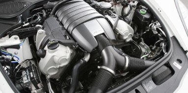
Hyundai D4AF Specifications
| Engine Model: Hyundai D4AF |
| Engine Type: 4-cycle inline 4-cylinder OHV 8-valve liquid-cooled diesel |
| Total Displacement: 217.7 cu.in (3.57 L) |
| Rated Engine Power: 100 Hp (74 kW) at 3400 rpm |
| Fuel System Type: Indirect injection |
____________________________________________________________________________________
The Hyundai D4AF is a 3.6-liter, inline-four, naturally
aspirated diesel engine that served as a foundational powerplant for Hyundai’s
light-to-medium duty commercial vehicle lineup throughout the 1990s and early
2000s.
Derived from the Mitsubishi 4D32 design under a long-standing technical
collaboration, this engine was engineered for the demanding requirements of
truck and bus applications where durability, serviceability, and low-end torque
are paramount. Its mechanical simplicity and robust construction established it
as a reliable workhorse in markets across Asia, the Middle East, and Latin
America.
The D4AF is characterized by its use of indirect injection (IDI) technology with
a mechanical in-line injection pump, an overhead valve (OHV) valvetrain with
pushrods, and a fully gear-driven timing system. The absence of timing belts or
chains eliminates a common failure point and reduces scheduled maintenance
requirements.
The engine’s displacement of 3.6 liters, achieved through a large bore and
stroke combination, provides substantial low-speed torque suited for the
stop-start nature of urban delivery vehicles and the sustained loads encountered
in interurban transport. Its cast iron construction and pressed-in cylinder
liners allow for multiple overhauls, a critical feature for commercial vehicles
intended for high-mileage service lives.
The D4AF is a four-stroke, water-cooled, naturally aspirated diesel engine
configured for longitudinal mounting in rear-wheel-drive truck and bus chassis.
Its design prioritizes low-end torque, fuel economy, and mechanical longevity
over high-speed power output.
Engine Type: Inline-4, 4-cycle, water-cooled, naturally aspirated diesel
Displacement: 3,568 cc (217.7 cu.in)
Bore and Stroke: 104.0 mm (4.09 in) x 105.0 mm (4.13 in)
Compression Ratio: 18.0:1
Valvetrain: OHV, 8-valve (2 valves per cylinder) with pushrods and rocker arms
Fuel System: Mechanical indirect injection (IDI) with in-line injection pump
Firing Order: 1-3-4-2
Maximum Power: 74 kW (100 hp) at 3,400 rpm
Maximum Torque: 235 Nm (174 lb-ft) at 2,000 rpm
Compression Pressure: 3,040 kPa (441 psi) at 200 rpm
Idle Speed: 650-700 rpm
Maximum Engine Speed: 3,800 rpm
The cylinder block is manufactured from high-strength
cast iron with a deep-skirt design, extending the cylinder walls below the
crankshaft centerline to maximize structural rigidity under the high cylinder
pressures and mechanical loads of diesel operation.
The block features a closed-deck configuration, where the water jacket is fully
enclosed at the top deck surface, providing exceptional support for the cylinder
head gasket and preventing bore distortion under load. This construction is
essential for the D4AF’s intended application in commercial vehicles where
sustained high-load operation is routine.
Replaceable, pressed-in cast iron wet liners are employed, allowing for engine
rebuilding through liner replacement and overboring. The liner design isolates
the piston running surface from the main block casting, simplifying overhaul
procedures. The block incorporates integral mounting points for the gear train
housing at the front and the flywheel housing at the rear. A large-capacity cast
aluminum oil sump is bolted to the lower crankcase, contributing to the overall
structural stiffness of the engine assembly.
Block Material: Cast iron
Liner Type: Replaceable, pressed-in wet liners
Bore Diameter (standard): 104.0 mm (4.09 in)
Liner Protrusion above Block Deck: 0.05-0.12 mm (0.0020-0.0047 in)
Main Bearing Caps: Cast iron, with two bolts per cap
Crankshaft: Forged steel crankshaft with five main bearings and eight
counterweights. A torsional vibration damper is mounted at the front end to
control harmonic vibrations. Connecting Rods: Forged steel, I-beam design with
precision-bored big ends. Pistons: Cast aluminum alloy with a steel top ring
carrier for durability. Pistons incorporate a swirl recess in the crown to match
the indirect injection combustion chamber design.
The cylinder head is constructed from cast iron,
matching the thermal expansion characteristics of the block to ensure reliable
head gasket sealing over a wide temperature range. The head employs a cross-flow
design with the intake manifold on the left side and the exhaust manifold on the
right side. The combustion system utilizes indirect injection (IDI) with
individual swirl chambers - also referred to as pre-combustion chambers -
integrated into the cylinder head for each cylinder.
These chambers are formed by steel inserts that provide a highly turbulent
environment for fuel-air mixing before combustion propagates into the main
cylinder. This IDI design enables smooth, quiet combustion and allows for the
use of mechanical injection equipment with lower injection pressures.
The valvetrain is an OHV configuration with a single camshaft located within the
cylinder block. The camshaft actuates the valves through hydraulic or mechanical
tappets, pushrods, and forged steel rocker arms. Two valves per cylinder - one
intake and one exhaust - are arranged in a parallel configuration. The valves
are seated on hardened steel inserts pressed into the cylinder head. Valve
clearance is set manually using adjustment screws on the rocker arms.
Head Material: Cast iron
Combustion Chamber Type: Indirect injection with steel swirl chamber inserts
Valve Configuration: OHV, 2 valves per cylinder
Valve Diameter (Intake): 42.0 mm (1.65 in)
Valve Diameter (Exhaust): 36.0 mm (1.42 in)
Valve Stem Diameter: 9.0 mm (0.35 in)
Valve Seat Angle: 45 degrees
Glow Plug Type: Sheathed type with pencil-style heating element
The D4AF employs a mechanical indirect injection fuel
system centered around an in-line injection pump. This pump design, commonly a
Bosch P-type or licensed equivalent, uses individual plungers and barrels for
each cylinder, delivering precisely metered fuel to the injectors. The pump is
driven directly by the engine’s gear train and incorporates a mechanical
governor that regulates fuel delivery based on engine speed and load, as well as
a cold-start device that advances injection timing when the engine is cold.
High-pressure steel injection lines connect the pump to nozzle-type injectors
mounted in the cylinder head. Each injector contains a spring-loaded nozzle that
opens at a predetermined pressure to atomize fuel into the swirl chamber. A
manual primer pump is integrated into the fuel system to facilitate bleeding air
after filter changes or fuel system service. A sedimenter and a replaceable fuel
filter are mounted in the fuel supply line to remove water and contaminants.
Injection Type: Mechanical indirect injection
Injection Pump: In-line type (Bosch P-series or equivalent)
Number of Plungers: 4
Injection Timing: 12-14 degrees before top dead center (static)
Injection Pressure (nozzle opening): 10.8-11.8 MPa (1,566-1,711 psi)
Fuel Requirement: Diesel fuel with minimum cetane number of 45
Fuel Filter: Replaceable cartridge type with integrated water sedimenter
The lubrication system is a fully pressurized, wet-sump
design utilizing a gear-type oil pump mounted to the front of the crankshaft
within the gear train housing. The oil pump draws lubricant from a
large-capacity stamped steel or cast aluminum oil pan through a mesh strainer. A
full-flow, replaceable oil filter is mounted externally, with an integral bypass
valve that allows oil flow to continue if the filter becomes restricted.
Pressurized oil is distributed through internal galleries to the crankshaft main
bearings, connecting rod bearings, camshaft bearings, and the timing gear train.
A piston cooling system is incorporated, consisting of oil jets that direct a
continuous spray of oil to the underside of each piston crown. This feature is
essential for managing the thermal load on the pistons during sustained
high-load operation. A water-cooled oil cooler is integrated between the oil
filter mounting and the cylinder block to stabilize oil temperature under
varying operating conditions.
Oil Type: Diesel-rated SAE 15W-40 or 10W-30 (API CD or higher)
Oil Capacity: 8.0-9.5 liters (8.5-10.0 US qt), depending on oil pan
configuration
Oil Pressure (at 3,000 rpm): 294-392 kPa (42.6-56.9 psi)
Oil Pressure (at idle): 98 kPa (14.2 psi) minimum
Oil Pump Type: Gear-type, gear train-driven
Piston Cooling Jets: Active at all engine speeds
The cooling system is a pressurized, liquid-cooled
design engineered to handle the substantial thermal load of a 3.6-liter diesel
engine in commercial vehicle applications. A large-capacity cross-flow radiator
with a mechanical fan is employed, with the fan typically driven by a viscous
coupling to reduce parasitic power loss when cooling demand is low. A
centrifugal-type water pump, driven by the gear train, circulates coolant
through the cylinder block, cylinder head, and oil cooler.
A wax-pellet thermostat regulates coolant flow to maintain optimal operating
temperature, with a bypass circuit that allows the engine to warm efficiently.
The system is designed to provide uniform cooling across all four cylinders,
minimizing thermal distortion of the cast iron components. A coolant recovery
tank is integrated to maintain system pressure and prevent coolant loss.
Coolant Type: Ethylene-glycol based antifreeze with corrosion inhibitors
Coolant Capacity: 13.0-15.0 liters (13.7-15.9 US qt), including radiator and
heater circuit
Thermostat Opening Temperature: 76-82 °C (169-180 °F)
Thermostat Full-Open Temperature: 90 °C (194 °F)
Radiator Cap Pressure: 88-108 kPa (12.8-15.7 psi)
Water Pump Type: Centrifugal, gear train-driven
| Intake and Exhaust Systems |
Intake System: Air is drawn through a heavy-duty
dry-type paper element air filter with a service indicator. The intake manifold
is a cast iron design with a large plenum chamber to ensure even air
distribution to all cylinders.
Exhaust System: Cast iron exhaust manifold with individual runners collecting
into a single outlet. The exhaust system is designed for commercial vehicle
applications with provisions for high exhaust temperatures under sustained load.
Timing Drive: The camshaft and injection pump are
driven directly by a train of precision-cut gears from the crankshaft. The gear
train is housed in a cast aluminum front cover and consists of a crankshaft
gear, an idler gear, a camshaft gear, and an injection pump drive gear. This
system is maintenance-free, requiring no periodic replacement, and provides
precise timing synchronization between rotating components.
Overall Length: 890 mm (35.0 in)
Overall Width: 640 mm (25.2 in)
Overall Height: 920 mm (36.2 in)
Dry Weight (complete engine): 310 kg (683 lb)
Oil Change Interval: 5,000 km (3,000 mi) under normal
commercial operating conditions; 3,000 km (1,800 mi) under severe conditions.
Oil Filter Change: At every oil change. Engine Coolant Replacement: 60,000 km
(40,000 mi) or 2 years. Air Filter Replacement: 30,000 km (18,000 mi) or as
indicated by service indicator.
Fuel Filter Replacement: 20,000 km (12,000 mi) or as indicated by sedimenter
inspection. Fuel Sedimenter Drain: Every 5,000 km (3,000 mi) to remove
accumulated water and sediment. Injection Pump Timing: Should be verified after
any service affecting gear train alignment using dynamic timing equipment. Glow
Plug Inspection: 60,000 km (40,000 mi) for resistance and heating performance.
Valve Clearance Adjustment: Inspect and adjust every 20,000 km (12,000 mi).
Intake: 0.40 mm (0.016 in) cold. Exhaust: 0.40 mm (0.016 in) cold. Valve
Adjustment Procedure: Clearance is set by loosening the rocker arm lock nut and
turning the adjustment screw. The engine must be at operating temperature or
cold as specified. Drive Belt (Accessory) Inspection: Every 10,000 km (6,000 mi)
for tension, cracking, and glazing.
Cylinder Head Bolts (M14 x 2.0), 1st pass: 60 Nm (44
lb-ft).
Cylinder Head Bolts (M14 x 2.0), 2nd pass: 120 Nm (89 lb-ft).
Main Bearing Cap Bolts (M14 x 2.0): 80 Nm (59 lb-ft).
Connecting Rod Cap Bolts (M12 x 1.5): 40 Nm (30 lb-ft).
Camshaft Bearing Cap Bolts (M10 x 1.25): 45-50 Nm (33-37 lb-ft).
Rocker Arm Shaft Bolts (M10 x 1.25): 35-40 Nm (26-30 lb-ft)
Intake Manifold Nuts (M10 x 1.25): 35-40 Nm (26-30 lb-ft).
Exhaust Manifold Nuts (M10 x 1.25): 35-40 Nm (26-30 lb-ft).
Glow Plugs: 20-25 Nm (15-18 lb-ft).
Oil Pan Bolts (M8 x 1.25): 20-25 Nm (15-18 lb-ft).
Water Pump Bolts (M10 x 1.25): 30-35 Nm (22-26 lb-ft).
Injection Pump Mounting Nuts (M10 x 1.25): 35-40 Nm (26-30 lb-ft).
Injection Line Nuts: 20-25 Nm (15-18 lb-ft).
Crankshaft Pulley Bolt (M20 x 1.5): 350-400 Nm (258-295 lb-ft).
Flywheel Bolts (M12 x 1.25): 50 Nm (37 lb-ft).
Front Gear Train Cover Bolts (M8 x 1.25): 20-25 Nm (15-18 lb-ft).
The D4AF engine was utilized extensively in Hyundai’s
light-to-medium duty commercial vehicle range throughout the 1990s and early
2000s. Its applications span truck, bus, and specialty vehicle platforms.
Hyundai Mighty (FE444, FE445, FE470 series): 2-ton to 2.5-ton truck variants
with naturally aspirated diesel configuration.
Hyundai County (B-series buses): Medium-duty bus applications.
Hyundai Chorus (A-series buses): Light-duty bus and minibus applications.
Hyundai H100 / Porter (heavy-duty variants): Select markets with 3.6-liter
naturally aspirated diesel option.
Hyundai H350 (early generations): Light truck variants in select markets.
____________________________________________________________________________________
| Car Engines Technical Specifications |
| Small Engines Technical Specifications |
| Industrial Engines Technical Specifications |
| Outboard Engines Technical Specifications |